Oil and chip skimmer

a technology of oil and chips, applied in the direction of water cleaning, liquid displacement, separation process, etc., can solve the problems of metal chips, coolant collection, undesired labor hours,

Inactive Publication Date: 2005-05-03
ABANAKI CORP
View PDF15 Cites 10 Cited by
  • Summary
  • Abstract
  • Description
  • Claims
  • Application Information

AI Technical Summary

Benefits of technology

[0011]In an alternative embodiment, the skimmer includes a second wiper mounted to the frame and positioned upstream from the first wiper. The second wiper includes a ring having a center axis and a plurality of spokes extending radially from the ring toward the center axis. With the tube in motion, the spokes act to rack large chunks of accumulated metal chips off the tube prior to the tube contacting the first wiper. To enhance the performance of the skimmer as desired, the first wiper may be constructed as a scraper or a brush.

Problems solved by technology

While oil skimmers of belt and other types have been relatively successful in removing oil from water surfaces, they do not address the issue of metal chips that accumulate within a coolant collection tank as a consequence of machining operations.
Consequently, this type of manual removal requires undesired labor hours and may increase machine down time within these machining centers.

Method used


Image

  • Oil and chip skimmer
  • Oil and chip skimmer
  • Oil and chip skimmer

Examples


Embodiment Construction

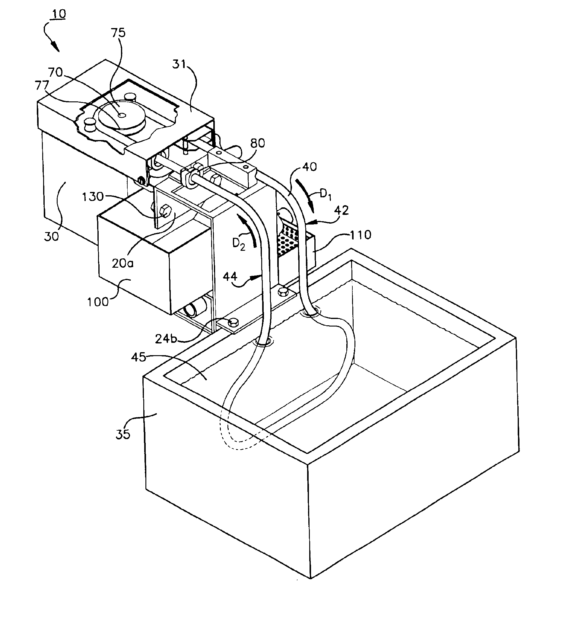
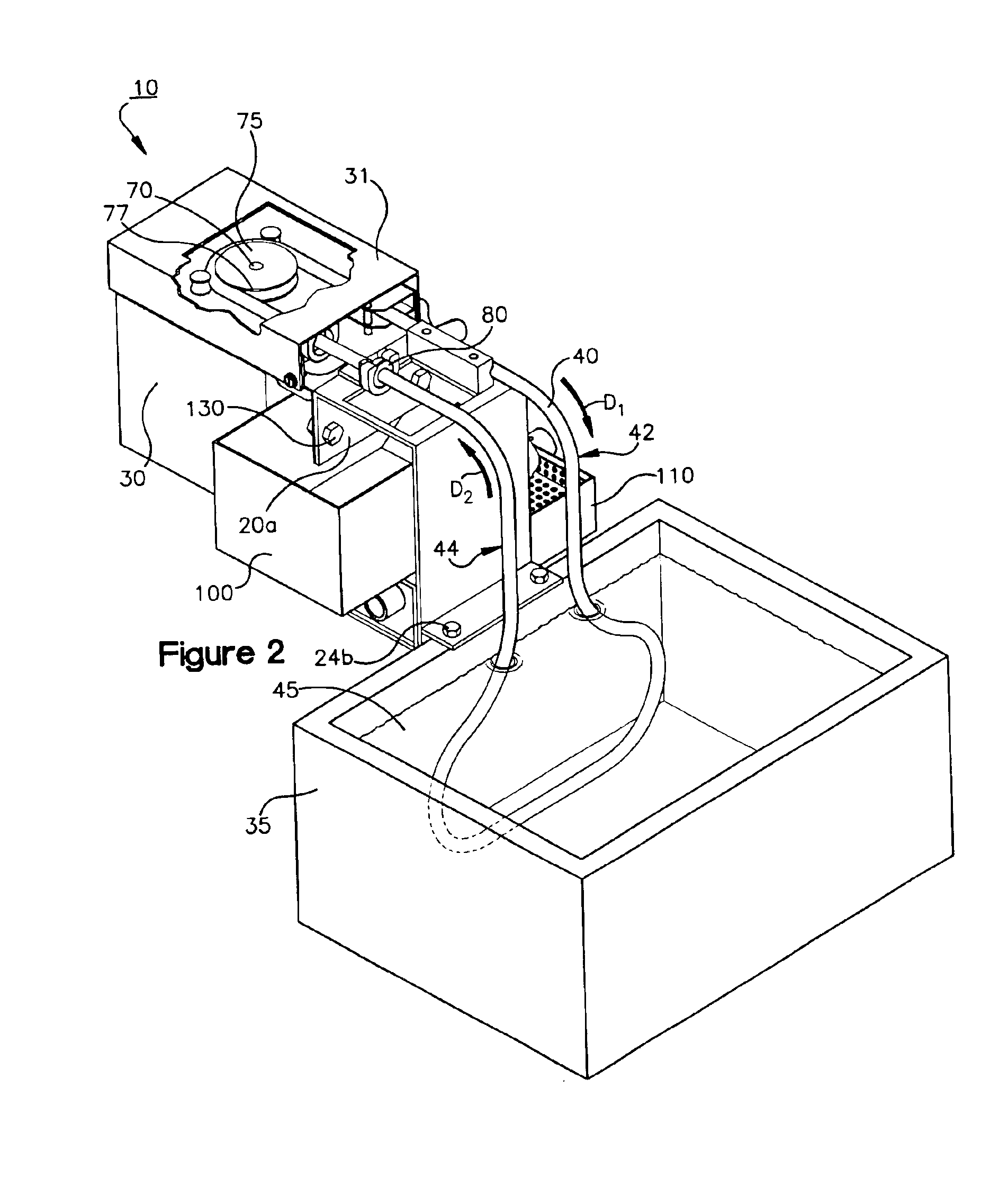
[0028]Referring now to the drawings, an oil and chip skimmer 10 constructed in accordance with the preferred embodiment of the present invention is illustrated. The skimmer as shown is well-suited for removing paramagnetic chips and oil contaminants that accumulate in a collection tank during machining and tooling operations. The skimmer advantageously removes these contaminants from the tank without manual operations as required in the prior art.

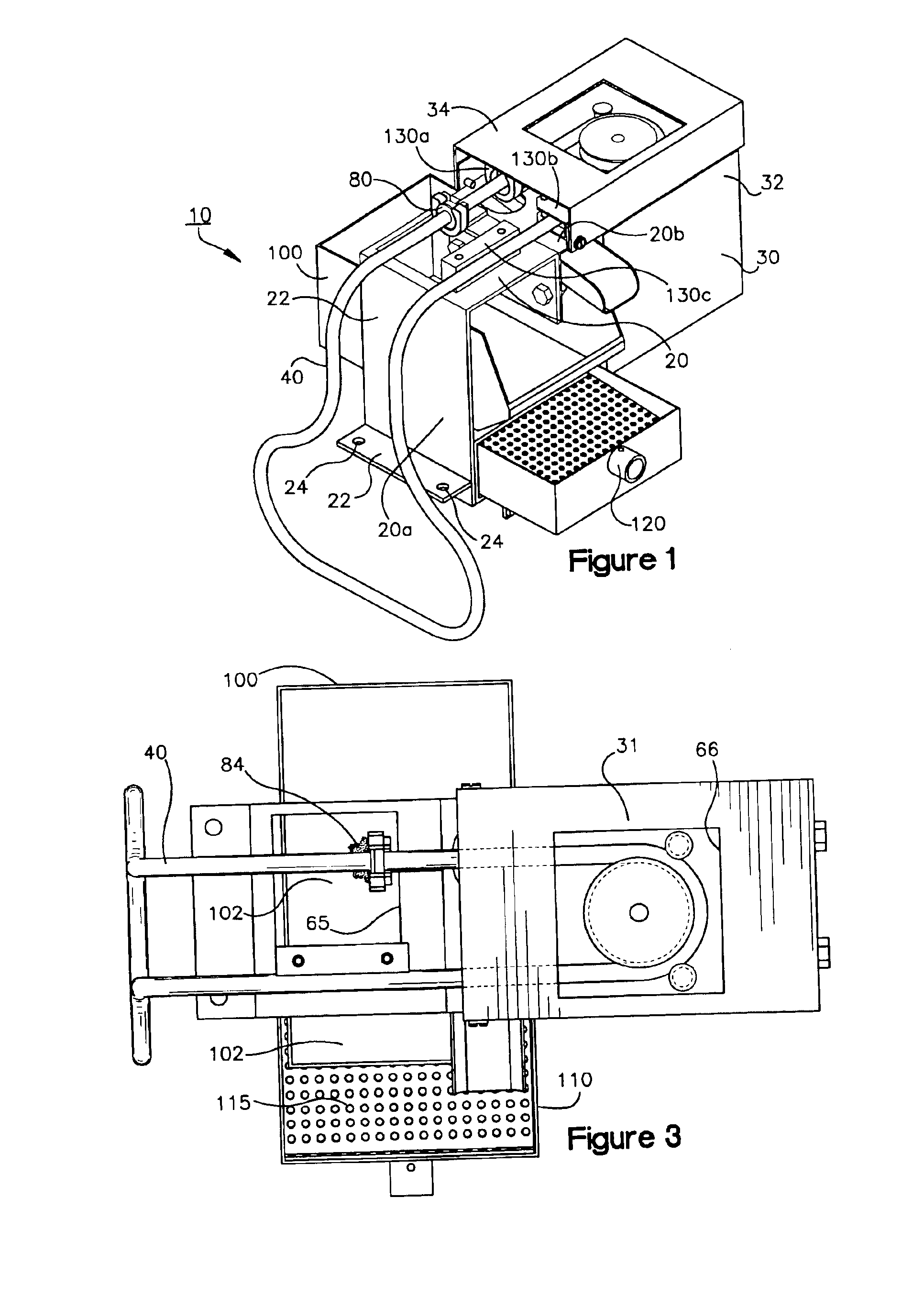
[0029]As illustrated in FIG. 1, the skimmer includes a frame structure 20. The frame 20 is formed from sheet metal and is utilized to position the skimmer above a body of water, as shown in FIG. 2. In the embodiment illustrated, the frame 20 is formed by an identical first frame member 20a and second frame member 20b fastened together in a mirrored relationship. As best seen in FIG. 2, conventional hardware 130 is used to mount the first and second members 20a, 20b together. The first frame member 20a is illustrated prior to assembly in FIG...


PUM

PropertyMeasurementUnit
gravityaaaaaaaaaa
timeaaaaaaaaaa
paramagneticaaaaaaaaaa

Abstract

A skimmer for removing oil and paramagnetic chips from a contaminated body of machine tool coolant. The skimmer includes a frame and an endless tube partially trained within the frame that defines a travel path. The path of the tube includes a first section within the body of coolant and a second section out of the body of coolant. The skimmer further includes a magnet disposed within the tube, a drive system mounted to the frame and operatively coupled to the tube to power travel of the tube, and a wiper connected to the frame at a position along the travel path. The wiper is advantageously positioned adjacent to the tube such that the wiper removes oil and metal chips carried by the tube. A receptacle is includes that delineates a collection space positioned below the wiper to receive oil and metal chips.

Description

FIELD OF THE INVENTION[0001]The present invention is directed to a method and apparatus for separating contaminates from a liquid bath and more particularly is directed to a method and apparatus which are especially suited for removing metal chips and hydrocarbons from a collection tank of machine tool coolant.BACKGROUND[0002]Oil skimmers for removing oil and other hydrocarbons from surfaces of bodies of water and other liquids are known in the art. One application for these skimmers is in production and tooling centers in which machining operations are performed that use machine tool coolant. During these types of operations, a material amount of oil, metal chips and coolant is directed to a collection tank.[0003]Various oil skimmer styles have been employed to remove oil from water surfaces. Styles of conventional skimmers include belt type oil skimmers, such as those described in U.S. Pat. No. 5,378,371 to Hobson, issued Jan. 3, 1995, and in U.S. Pat. No. 5,645,733 to Hobson, iss...

Claims


Application Information

Patent Timeline
Patent Type & Authority Patents(United States)
IPC IPC(8): B01D41/00C02F1/40
CPCB01D21/0009B01D21/2433B01D21/245B03C1/03B03C1/0332B03C1/286Y10S210/923B03C2201/18
Inventor HOBSON, MARK T.
Owner ABANAKI CORP
Why Eureka
Try Eureka