Joining of bipolar plates in proton exchange membrane fuel cell stacks

a proton exchange membrane and fuel cell technology, applied in the field of fuel cell stacks, can solve the problems of increasing the cost of the fuel cell stack, so as to reduce the potential for oxidation of the electrically conductive layer and reduce the cost of plating materials

Inactive Publication Date: 2005-05-03
GM GLOBAL TECH OPERATIONS LLC
View PDF10 Cites 56 Cited by
  • Summary
  • Abstract
  • Description
  • Claims
  • Application Information

AI Technical Summary

Benefits of technology

[0008]In a preferred embodiment, silver is plated over the entire surface of the inner portion of each plate to form the electrically conductive layer. Silver plating can also be applied over only the coolant lands, or over both the coolant lands and the coolant channels of the inner portions of both plate pairs. Gold can be substituted for silver plating material, however, silver is preferred over gold material for the electrically conductive layer to reduce plating material cost. The following are other preferred plating materials that can be substituted for either silver or gold: silver alloys, gold alloys, tin, tin alloys, lead and lead alloys.
[0009]The perimeter seal prevents a stack reactant gas from contacting and oxidizing the electrically conductive layer (e.g., the silver layer). The seal is preferably disposed around the entire perimeter of the inner portion of both facing surfaces of a bipo

Problems solved by technology

A disadvantage of using gold for the plating material is both the thickness and the cost of the gold required for the plating.
If pressure alone is used to join the plate pairs to form a bipolar plate assembly, cost of the fuel cell stack is increased due to the cost of gold and the thickness of the gold plating material required to provide adequate land-to-land contact surface.
Note that the reactants (humidified air) and coo

Method used


Image

  • Joining of bipolar plates in proton exchange membrane fuel cell stacks
  • Joining of bipolar plates in proton exchange membrane fuel cell stacks
  • Joining of bipolar plates in proton exchange membrane fuel cell stacks

Examples


Embodiment Construction

[0018]The following description of the preferred embodiment(s) is merely exemplary in nature and is in no way intended to limit the invention, its application, or uses.

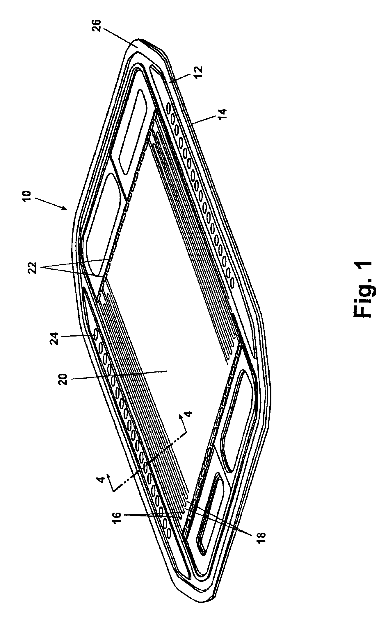
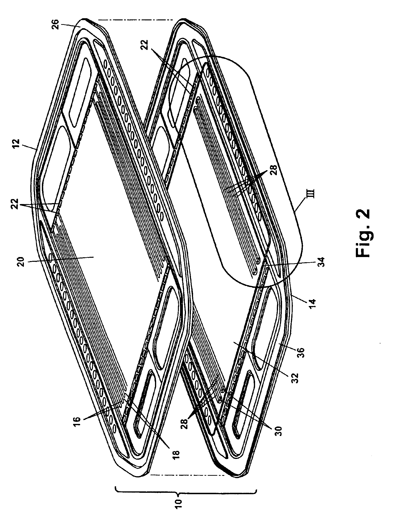
[0019]Referring to FIG. 1, a bipolar plate assembly 10 of a preferred embodiment of the present invention is shown. The bipolar plate assembly 10 includes a first plate 12 and a second plate 14 forming a plate pair. A plurality of first plate reactant gas channels 16 are each separated by a plurality of first plate reactant gas lands 18 on a first plate outer surface 20 of the first plate 12. A similar plurality of reactant gas channels and lands are formed on an outer surface of the second plate 14 (shown in reference to FIGS. 4 and 5).

[0020]A plurality of reactant gas ports 22 and a plurality of coolant ports 24 are also disposed on the first plate outer surface 20. It is noted that a plurality of configurations of the reactant gas channels 16, the reactant gas lands 18, the reactant gas ports 22, and the coolant po...


PUM


Abstract

A bipolar plate assembly for a proton exchange membrane fuel cell stack advantageously connects electrically conductive plate surfaces, without the requirement to weld or braze the plate pairs. Each plate has alternating coolant channels and lands formed on an inside facing surface. An electrically conductive layer is deposited over at least the coolant channels and lands. Pairs of plates are aligned having facing electrically conductive layers. A fluid seal is disposed between the inside facing surfaces about a perimeter of the coolant channels. Each plate pair is compressed to form a plurality of electrical bond lines between adjacent lands within the perimeter seal. The perimeter seal prevents stack reactant gas oxygen from contacting and oxidizing the electrically conductive layer. A dielectric coolant is also used to reduce oxidation of the electrically conductive layer.

Description

FIELD OF THE INVENTION[0001]The present invention relates in general to fuel cell stacks and more specifically to an apparatus and method of construction of a bipolar plate for a proton exchange membrane fuel cell stack.BACKGROUND OF THE INVENTION[0002]Proton exchange membrane (PEM) fuel cell stacks are commonly configured having a plurality of fuel cell elements in a stacked configuration. The fuel cell elements commonly include a pair of PEM elements separated by a bipolar plate. Bipolar plates are commonly constructed having a pair of plates joined by adhesive seal, by brazing, and by welding.[0003]Bipolar plates are commonly constructed with an upper plate and a lower plate. Both the upper plate and the lower plate include a plurality of reactant gas passages or grooves formed in the outer facing surfaces of the two plates. A plurality of coolant channels or portions of coolant channels are formed on the inner facing surfaces of the bipolar plates. When the two plate pairs are j...

Claims


Application Information

Patent Timeline
IPC IPC(8): H01M2/00H01M2/08H01M2/14H01M8/04H01MH01M8/02
CPCH01M8/0206H01M8/0228H01M8/0247H01M8/0267H01M8/0271Y02E60/50H01M8/0263H01M8/026H01M8/241H01M8/2483H01M8/0273H01M8/2404
Inventor ELHAMID, MAHMOUD H. ABDMIKHAIL, YOUSSEF M.BLUNK, RICHARD H.LISI, DANIEL J.
Owner GM GLOBAL TECH OPERATIONS LLC
Why Eureka
Try Eureka