Magnetoresistive device and method for producing the same, and magnetic component

a magnetoresistive device and magnetic component technology, applied in the direction of magnetic bodies, transportation and packaging, substrate/intermediate layers, etc., can solve the problems of insufficient thermal stability of conventional mr devices, high mr (magneto resistance) not being realized, and the oxidation of the lower ferromagnetic film beyond the aluminum film, etc., to achieve easy control, shorten the time for forming the high-resistivity layer, and increase the diffusion velocity of elemen

Inactive Publication Date: 2005-05-03
PANASONIC CORP
View PDF14 Cites 10 Cited by
  • Summary
  • Abstract
  • Description
  • Claims
  • Application Information

AI Technical Summary

Benefits of technology

[0038](a-2) reacting the surface of the magnetic layer with the element LONC thereby to form the first magnetic layer and the high-resistivity layer. According to this method, even when the surface of the magnetic layer is not flat, a high-resistivity layer having an approximately uniform thickness can be formed easily. Furthermore, in this method, it is preferable that in the step (a-2), the element RCP is allowed to diffuse into the first magnetic layer so that the concentration of the element RCP gradually increases to the side of the high-resistivity layer in the first magnetic layer. Furthermore, in this case, it is preferable that in the step (a-2), when reacting the surface of the magnetic layer with the element LONC, the surface of the magnetic layer is heated at a temperature of at least 50° C. but not higher than 800° C. By carrying out such a heating, the diffusion velocity of the element RCP can be increased, and the time for forming the high-resistivity layer can be shortened.
[0039]In the method of the present invention, it is preferable that in the step (a), the first magnetic layer is formed by evaporation or sputtering so that the concentration of the element RCP is high on the side of the high-resistivity layer in the first magnetic layer. Accordingly, the concentration distribution of the element RCP in the first magnetic layer can be controlled easily by controlling the deposition rate of the element RCP.
[0040]Furthermore, the present invention provides a magnetic component including a magnetoresistive device, wherein the magnetoresistive device is obtained by heating the magnetoresistive device of the present invention at a temperature of at least 200° C. According to the magnetic component of the present invention, each magnetic component easily can obtain an arbitrary resistance meeting its use as well as a high MR. For example, a resistance of several ten-ohms to several mega-ohms times square micron for RA (resistance area) is required in MRAM. Also, a resistance of several tens of milli-ohm to several ohms times square micron is required in a magnetic head. Moreover, a high MR can be obtained even when its surface is relatively rough.

Problems solved by technology

However, a high MR (magneto resistance) has not been possible to realize.
However, with a conventional process for oxidizing an aluminum film, the lower ferromagnetic film is likely to be oxidized beyond the aluminum film when the aluminum film is thin.
Furthermore, conventional MR devices do not have a sufficient thermal stability, and for example, when using them as MRAM, heat deterioration such as decreased MR property is caused during post-annealing of CMOS (at about 250 to 400° C.) or heating in the production of MR heads (at about 250° C

Method used


Image

  • Magnetoresistive device and method for producing the same, and magnetic component
  • Magnetoresistive device and method for producing the same, and magnetic component
  • Magnetoresistive device and method for producing the same, and magnetic component

Examples


first embodiment

[0060]In the first embodiment, an example of a magnetoresistive device of the present invention is described.

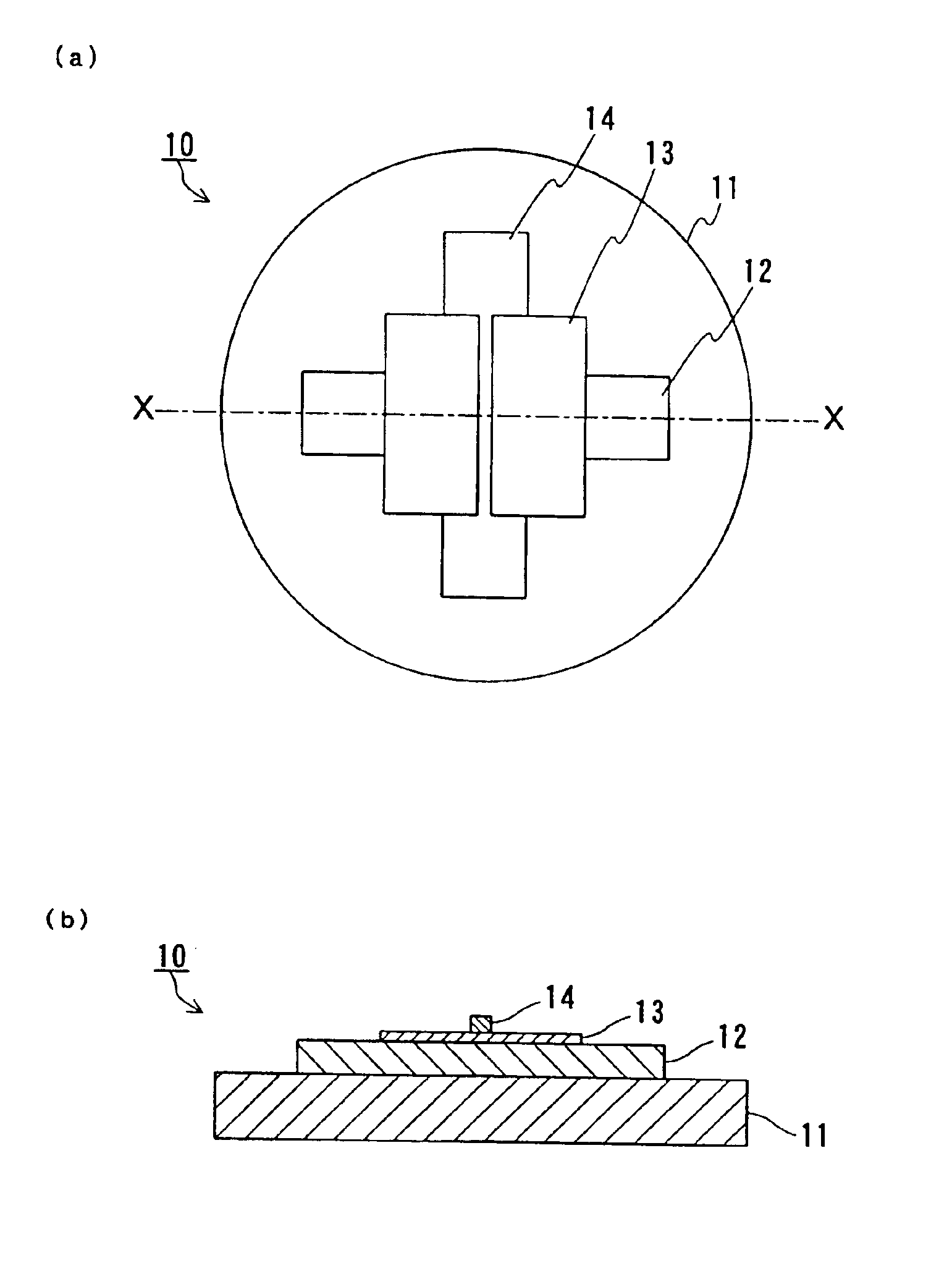
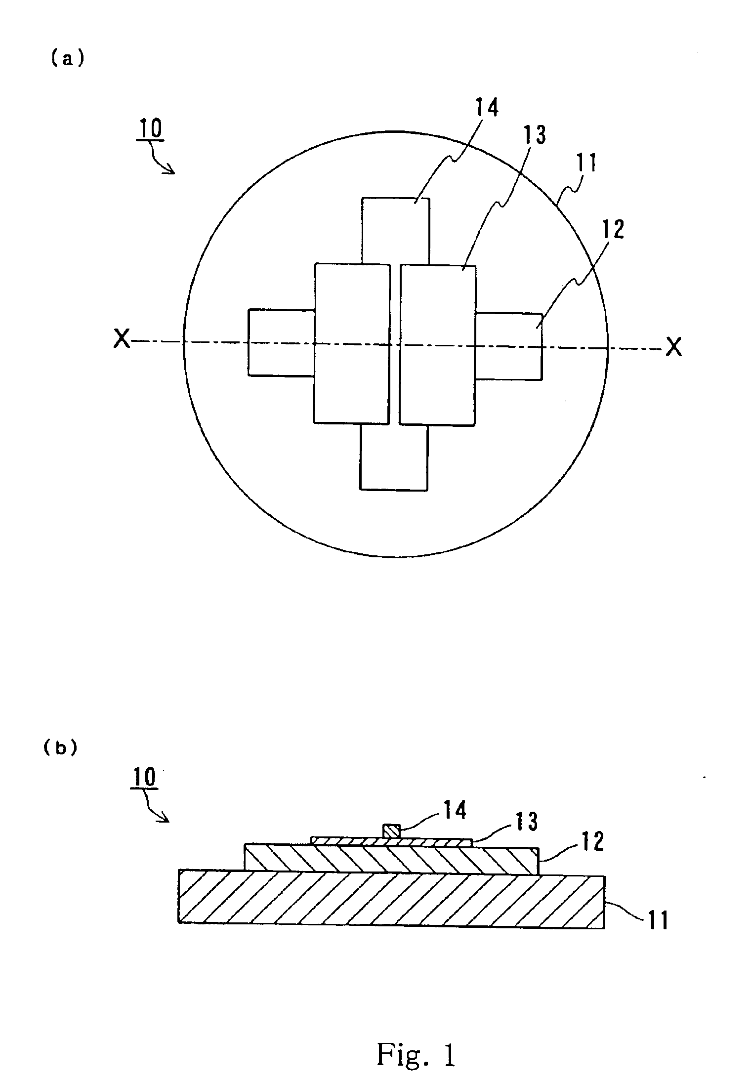
[0061]FIG. 1(a) shows a plan view of a magnetoresistive device 10 of a first embodiment. FIG. 1(b) shows a sectional view taken along the line X—X of FIG. 1(a).

[0062]Referring to FIG. 1, a magnetoresistive device 10 includes a substrate 11, and a first magnetic layer 12, a high-resistivity layer 13 and a second magnetic layer 14 laminated one by one on the substrate 11. In other words, the magnetoresistive device 10 includes the high-resistivity layer 13, and the first magnetic layer 12 and the second magnetic layer 14 arranged so as to sandwich the high-resistivity layer 13.

[0063]Various substrates may be used for the substrate 11. Specifically, for example, a single crystal (magnesia, sapphire, STO, etc.), polycrystal (e.g. AITIC substrate), amorphous (thermal oxide film of silicon), or conductive substrate (or an oxide of alumina or silicon formed on a base) may be employe...

second embodiment

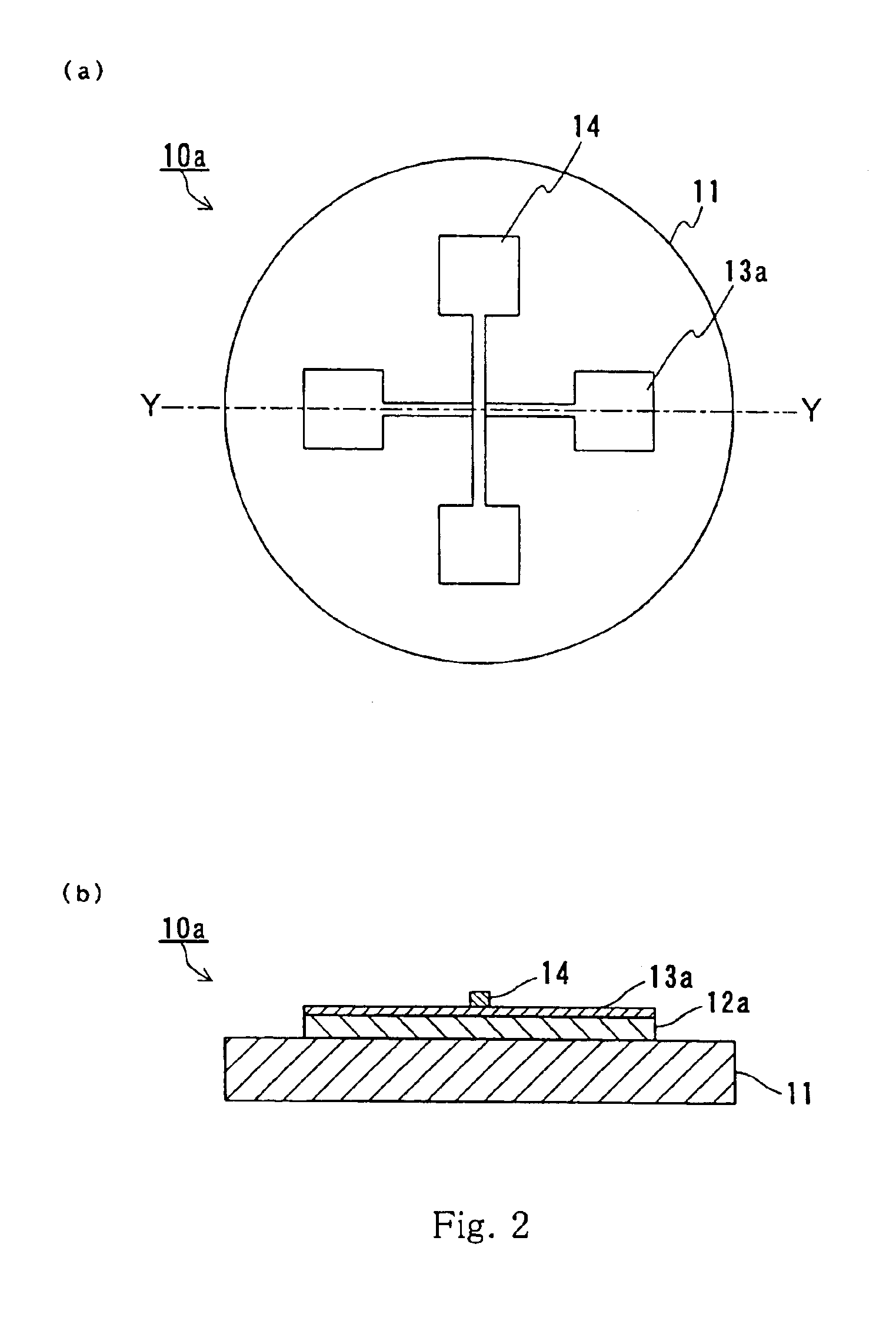
[0080]In the second embodiment, an example of the method for producing a magnetoresistive device according to the present invention is described. With respect to the same parts and elements as those described in the first embodiment, the same numerals are applied, and overlapped explanations thereof are omitted.

[0081]The method of the second embodiment includes:

[0082](a) forming a first magnetic layer 12a located on a substrate 11, and a high-resistivity layer 13 located on the first magnetic layer 12a and containing at least one element LONC selected from oxygen, nitrogen and carbon; and

[0083](b) forming a second magnetic layer 14 on the high-resistivity layer 13. The first magnetic layer 12a contains at least one metal element M selected from Fe, Ni and Co, and contains an element RCP different from the metal element M. As described in the first embodiment, the element RCP combines with the element LONC more easily in terms of energy than the metal element M. It is preferable that...

third embodiment

[0108]In the third embodiment, a magnetic component of the present invention is described.

[0109]The magnetic component of the present invention includes a magnetoresistive device. The magnetoresistive device is obtained by heating the magnetoresistive device of the present invention described in the first embodiment at a temperature of at least 200  C.


PUM

PropertyMeasurementUnit
temperatureaaaaaaaaaa
thicknessaaaaaaaaaa

Abstract

A magnetoresistive device including a high-resistivity layer (13), a first magnetic layer (12) and a second magnetic layer (14), the first magnetic layer (12) and the second magnetic layer (14) being arranged so as to sandwich the high-resistivity layer (13), wherein the high-resistivity layer (13) is a barrier for passing tunneling electrons between the first magnetic layer (12) and the second magnetic layer (14), and contains at least one element LONC selected from oxygen, nitrogen and carbon; at least one layer A selected from the first magnetic layer (12) and the second magnetic layer (14) contains at least one metal element M selected from Fe, Ni and Co, and an element RCP different from the metal element M; and the element RCP combines with the element LONC more easily in terms of energy than the metal element M. Accordingly, a novel magnetoresistive device having a low junction resistance and a high MR can be obtained.

Description

[0001]This application is a divisional of application Ser. No. 09 / 744,513, filed January 24, 2001, now U.S. Pat. No. 6,528,326 which application(s) are incorporated herein by reference which is a 371 of PCT / JP00 / 03452 filed May 29, 2000.TECHNICAL FIELD[0002]The present invention relates to a magnetoresistive device and a method for producing the same, and a magnetic component.BACKGROUND ART[0003]A TMR (tunnel magnetic resistance) device is a device in which a very thin insulating layer is inserted between two ferromagnetic layers. A TMR device uses the phenomenon that the tunneling current flowing through the insulating layer is changed by the relative angle of magnetization of each metal element M.[0004]It has been expected in theory that when using a ferromagnetic metal element M having a high spin polarizability such as Fe or FeCO for the ferromagnetic layers, a high rate of change in magnetic resistance of at least 35% is obtained (M. Jullier, Phs. Lett. 54A (1975) 225). However...

Claims


Application Information

Patent Timeline
Patent Type & Authority Patents(United States)
IPC IPC(8): H01F10/00H01F10/32H01L43/00H01L43/12
CPCB82Y25/00H01L43/12H01F10/3254Y10T428/26H10N50/01H10N50/10
Inventor HIRAMOTO, MASAYOSHIMATSUKAWA, NOZOMUSAKAKIMA, HIROSHIADACHI, HIDEAKIODAGAWA, AKIHIRO
Owner PANASONIC CORP
Why Eureka
Try Eureka