
Structural hot melt material and methods

a technology of structural hot melt and materials, applied in the field of epoxy-based structural materials, can solve the problems of reducing the ability to provide structural reinforcement, corrosion protection, and limitations of traditional hot melt materials used in the art for structural member reinforcement, etc., and achieve the effect of reducing and/or eliminating the step and inhibiting corrosion

Inactive Publication Date: 2005-05-03
ZEPHYROS INC
View PDF113 Cites 103 Cited by
  • Summary
  • Abstract
  • Description
  • Claims
  • Application Information

AI Technical Summary

Benefits of technology

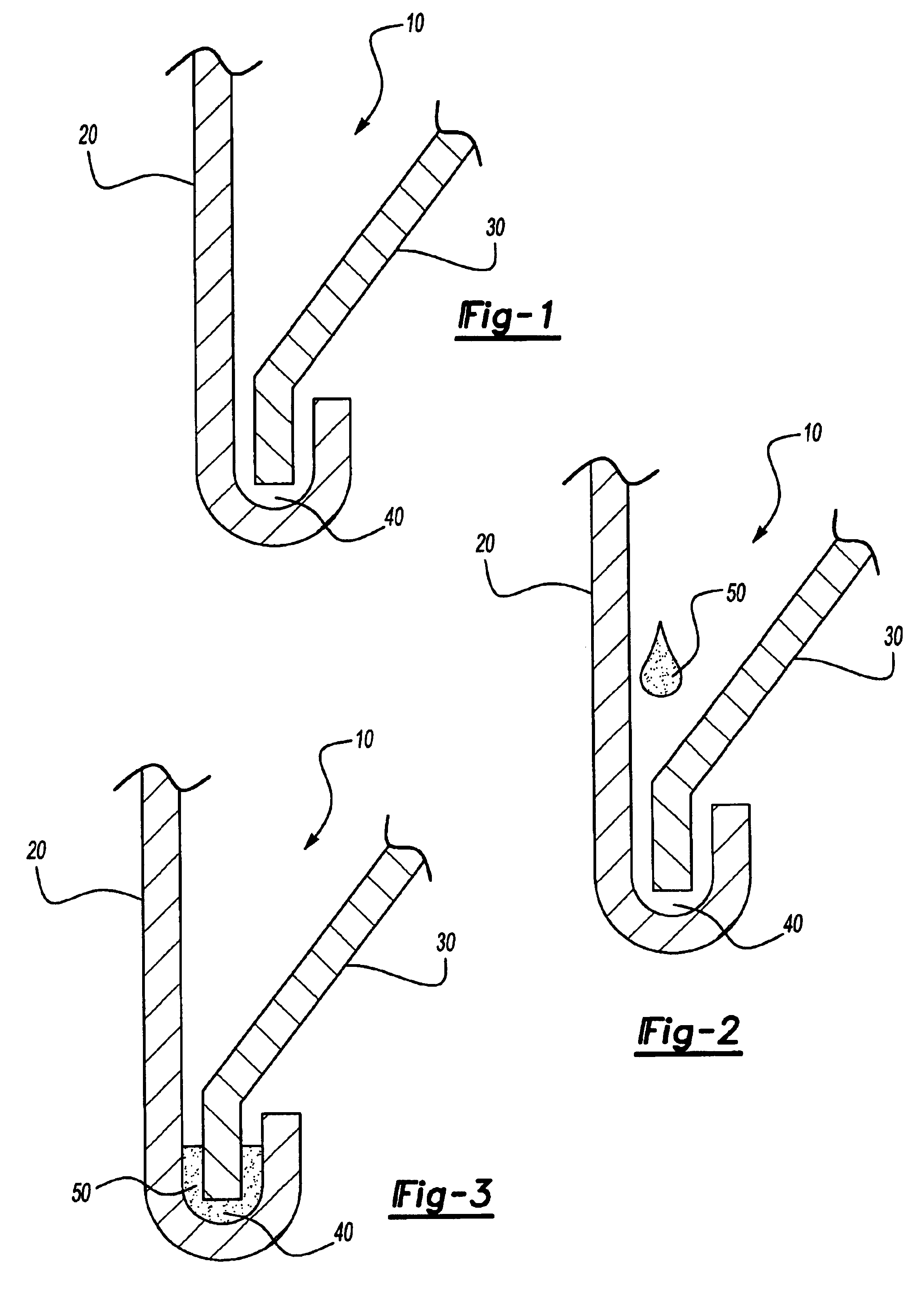
[0007]In yet another embodiment, the present invention provides a method of reinforcing structural members, particularly joints such as a hem flange joint in an automotive vehicle, which in a preferred embodiment, can serve to reduce and / or eliminate the step of pre-crimping the selected panels during the manufacturing process. The method comprises of: providing a structural member having two substrates forming a space to be joined; placing a structural material comprising, in parts by weight, less than about twenty percent (<20%) ethylene copolymer, less than about forty percent (<40%) epoxy, less than about thirty percent (<30%) epoxy-based resin, less than about two percent (<2%) blowing agent and from about one percent (1%) to about five percent (5%) curing agent, (and optionally includes any of the following components: less than about two percent (<2%) curing agent accelerator, from about twenty-five percent (25%) to fifty-five percent (55%) filler, and less than about one percent (<1%) of coloring agent) in proximity of the space to be joined or otherwise prepared for application; exposing the structural material to a heat or other energy source causing the structural material to flow, fill, and cure in the defined area or space to be joined thereby providing post-cure structural integrity and rigidity to the selected area or space of the land, marine, or aerospace vehicle. The method disclosed in the present invention provides an improved placement or disposition of hot-melt material throughout the selected flange or joint of automotive vehicles whereby the material is dispersed in a uniform manner and works in conjunction with the e-coat process to inhibit corrosion.

Problems solved by technology

Traditional hot melt materials that are used in the art for reinforcement of structural members, such as hem flange joints, have several limitations.
These prior art methods also may initiate re-melt flow upon exposure to heat, either unexpectedly or inadvertently, thereby reducing their ability to provide structural reinforcement and, more importantly, corrosion protection to the structural members at the desired location at a desired time and place during the manufacturing process.
Additionally, standard application of traditional hot melt materials may expose uncoated portions of structural members to corrosion and reduce their structural integrity.
However, these prior art materials and processes have a number of drawbacks and deficiencies which can ultimately diminish their efficiency and performance in a manufacturing facility.
For example, during standard application before the electrodeposition coating process, metal shavings, oil and other types of contamination can be trapped in the hem flange joint or some other targeted portion of a transportation vehicle or joint to be reinforced, which can cause electrodeposition coating not to adhere to the metal surface of the hem flange joint very well, thereby producing a site for corrosion initiation.
Moreover, the crimping process found in the prior art may serve to inhibit the flow or disposition of the selected material (including e-coat) within the joint or flange, since the now crimped panel can function as a barrier to proper flow of the materials, thereby leading to corrosion over time.
Corrosion can also occur when too much standard hot melt material is dispensed into the outer panel of hem flange joint.
The excess standard hot melt material is expelled during the crimping process and may flow onto the hem flange panels and lead to unwanted hem flange adhesive and wax stick materials being deposited into the flange and surrounding areas which can impede melt and sealing and lead to corrosion over the life of the vehicle.
This excess standard hot melt material is difficult to clean, thereby causing maintenance issues to arise in the manufacturing facility.
It can also result in inadequate adherence between the electrodeposition coating and the hem flange panels, thereby producing sites for corrosion initiation.
Accordingly, both an over abundance and a lack of proper placement of sufficient amounts of hot melt material within the selected joint can interfere with the e-coat process and lead to the development of corrosion areas within the vehicle over time.
Another limitation of the techniques found in the prior art is that the amount of traditional hot melt material being dispensed into the outer panel of hem flange joint may be inconsistent and non-uniform.
As discussed above, when there is too much traditional hot melt material dispensed, corrosion may occur as a result of poor e-coat deposition.
Likewise, if an insufficient amount of traditional hot melt material is dispensed into a flange or joint, corrosion is also likely to occur since a gap or gaps of dispersed material may develop during e-coat deposition resulting in uncoated metal in the hem flange.

Method used


Image

  • Structural hot melt material and methods

Examples


Embodiment Construction

[0011]As used herein, all concentrations shall be expressed as percentages by weight unless otherwise specified.

The Material

[0012]In a preferred embodiment, the material of the present invention includes less than about twenty percent (<20%) ethylene copolymer including, without limitation, ethylene-vinyl acetate (EVA) copolymer, ethylene vinyl acrylate, ethylene-methyl acrylate (EMA) copolymer, ethylene-butyl acrylate (EBA) copolymer, EMA / GMA, ethylene / α-olefin, and ethylene-ethyl acrylate (EEA). It is further preferred, but not required, that the ethylene copolymer is in a solid state or semi-solid state. The material of the present invention may also include less than about forty percent (<40%) epoxy, preferably in a solid state, such as bisphenol A, bisphenol F, novolac, modified urethane, or the like, including an adduct of such epoxy, such as a rubber adduct. Further, material disclosed in the present invention may optionally include less than about forty-five percent (<45%) o...


PUM

PropertyMeasurementUnit
Temperatureaaaaaaaaaa

Abstract

The present invention relates to a material, method, and application for reinforcement of structural members, especially joints such as a hem flange joint of an automobile. The method and material of the present invention comprises of combining, in parts by weight: less than about twenty percent (<20%) ethylene copolymer, less than about forty percent (<40%) epoxy, less than about thirty percent (<45%) epoxy-based resin, less than about two percent (<2%) blowing agent and from about one percent (1%) to about five percent (5%) curing agent (and optionally add any of the following components: less than about two percent (<2%) curing agent accelerator, from about twenty-five percent (25%) to fifty-five percent (55%) filler, and less than about one percent (<1%) of coloring agent). The application of the present invention comprises of: (1) providing a structural member having two substrates forming a space to be joined; (2) placing the material of the present invention in proximity of the space to be joined; (3) exposing the material to a heat source causing it to flow, fill, and cure in the defined area or space to be joined.

Description

FIELD OF THE INVENTION[0001]The present invention relates generally to epoxy-based structural materials that are used for reinforcement of structural members, especially joints, flanges, and other areas of transportation vehicles or other goods that could benefit from enhanced structural rigidity and reinforcement. More particularly, the present invention relates to an extruded or injection molded, non-tacky, epoxy-based structural material exhibiting improved mechanical properties (e.g., higher lap shear and higher T-Peel performance compared to products and methods found in the prior art) that can be dropped or otherwise disposed into any applicable joint, flange, or other targeted portion of the vehicle to impart structural rigidity and integrity to the selected joint or portion of the vehicle. The present invention further comprises a method or process whereby heat, emanating from the e-coat process, paint ovens, or other source of heat energy found in automotive manufacturing f...

Claims


Application Information

Patent Timeline
IPC IPC(8): B62D27/00B62D27/02C08J9/00C09J163/00C08L63/00C08J9/10C08G59/50C08K3/00C08K5/23C09J5/00C09J11/04C09J11/06C09J123/08
CPCB62D27/026C08J9/0066C09J163/00C08L63/00C08J2207/02C08J2363/00Y10T156/1722Y10T428/2481Y10T156/1724C08L2666/04Y10T428/249953Y10T428/249999Y10T428/249954Y10T428/249958
Inventor CZAPLICKI, MICHAEL J.KOSAL, DAVID J.ANTRIM, JEANNE
Owner ZEPHYROS INC
Learn More