

Optical system for lasers
- Summary
- Abstract
- Description
- Claims
- Application Information
AI Technical Summary
Benefits of technology
Problems solved by technology
Method used
Image

Examples
Embodiment Construction
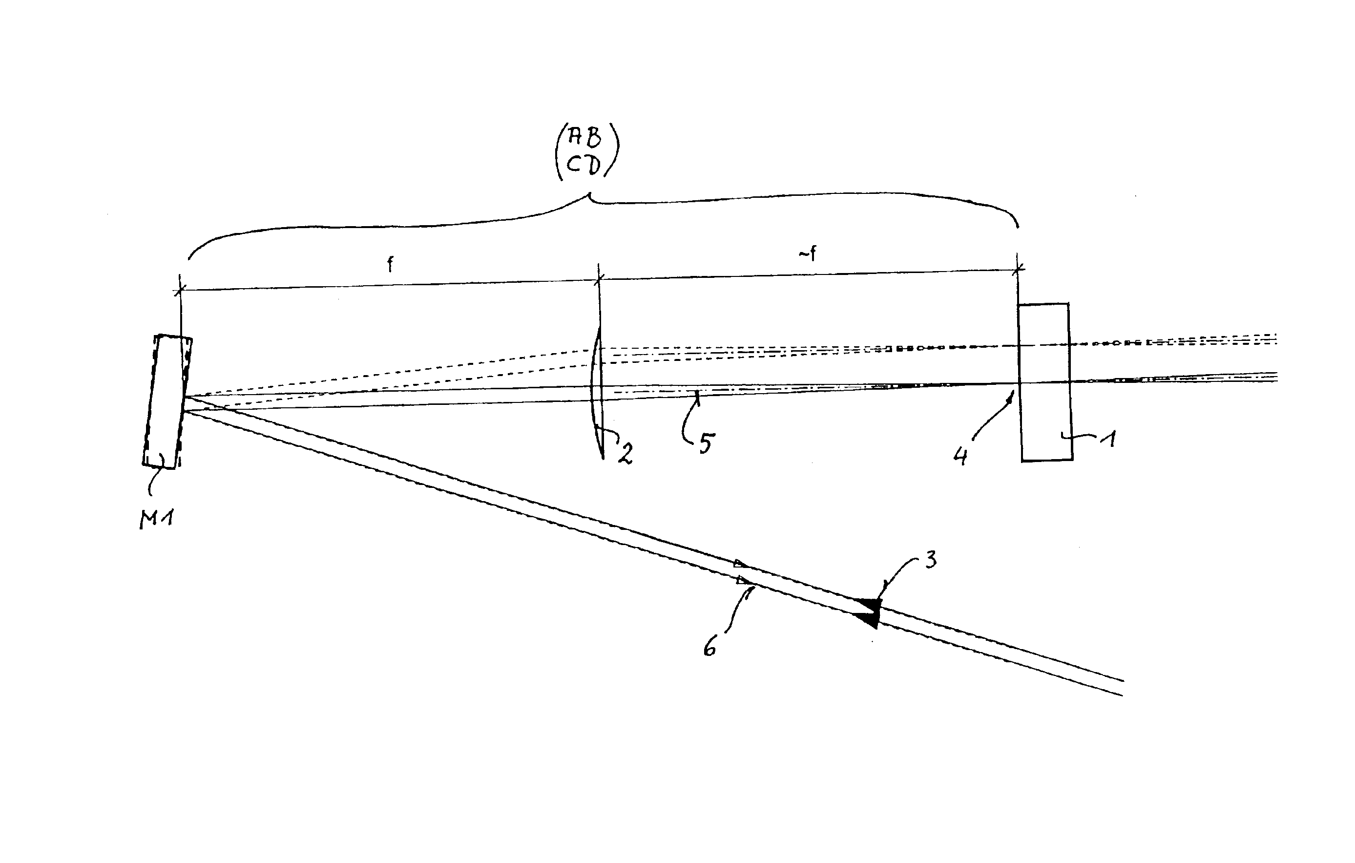
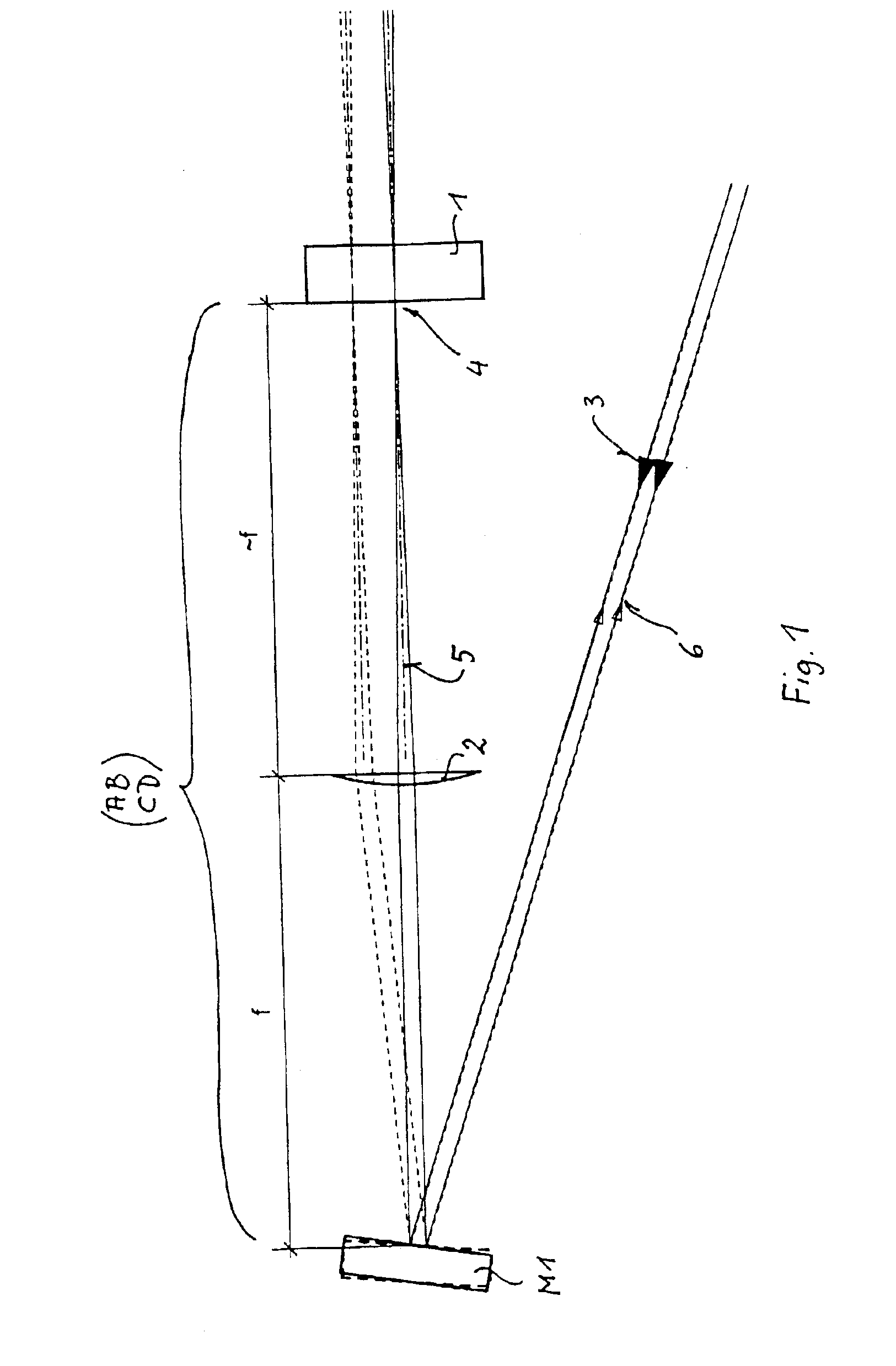
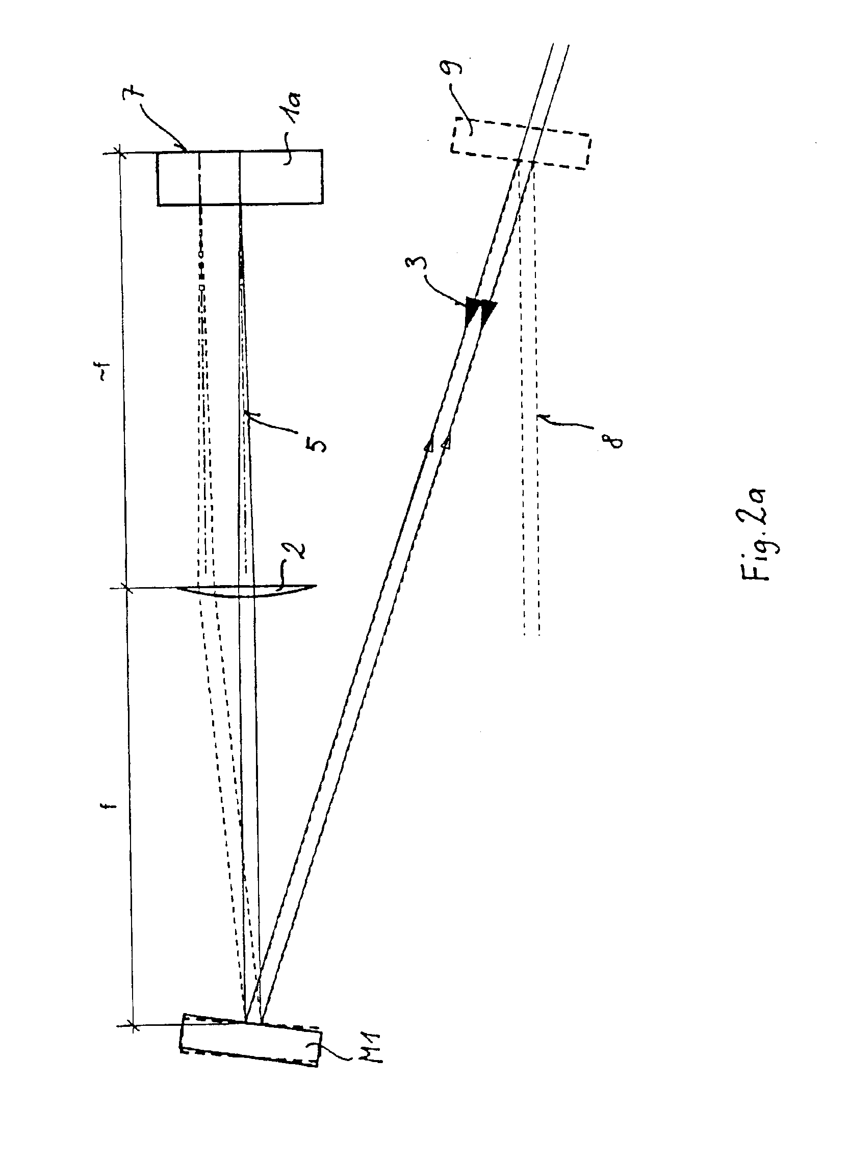
[0018]Scheme I: Scheme I of this invention is shown in FIG. 1. Here a reflective optical material 1 is used which is exposed to incident light being imaged or focused through a lens 2. If an incident beam 3 is collimated before reaching the lens 2, the lens 2 will focus the incident beam approximately onto a spot 4 on the optical material 1 (depending on the degree of collimation), the optical material 1 being positioned approximately at a distance corresponding to the focal length f away from the lens 2. If a reflective mirror M1 is put before the lens 2 at a distance corresponding to about the focal length f of the lens, then the spot 4 on the optical (laser) material 1 can be shifted simply by adjusting the angle of the reflecting mirror M1. If M1 is positioned at a distance away from the lens that corresponds exactly to f, the beam propagation axis 5 after the lens 2 (before the optical material 1) does not change its angle at all. Thereby, any change of the angle of the mirror ...
PUM
 Abstract
Description
Claims
Application Information