Piezoelectric electroacoustic transducer

a transducer and electroacoustic technology, applied in piezoelectric/electrostrictive transducers, generators/motors, diaphragms, etc., can solve the problems of a higher resonant frequency, low acoustic conversion efficiency of diaphragms, and difficulty in having compact structures and sound characteristics having low resonant frequencies, so as to prevent fluctuation or variation of frequency characteristics

Inactive Publication Date: 2005-05-03
MURATA MFG CO LTD
View PDF20 Cites 27 Cited by
  • Summary
  • Abstract
  • Description
  • Claims
  • Application Information

AI Technical Summary

Benefits of technology

[0017]In order to overcome the problems described above, preferred embodiments of the present invention provide a piezoelectric electroacoustic transducer which prev

Problems solved by technology

However, since such a diaphragm generates bending vibrations by restraining the piezoelectric plate generating square-type vibrations with the metal plate having an area that does not vary, the diaphragm has a low acoustic conversion efficiency and also has difficulties in having a compact structure and a sound characteristic having a low resonant frequency.
In addition, the periphery of the diaphragm is restrained by the casing, causing a problem of a higher resonant frequency.
However, because of a unimorph piezoelectric diaphragm, the diaphragm has difficulties in achieving high acoustic conversion efficiency and a compact structure.
Also, since the diaphragm and the film are both round, their deforme

Method used


Image

  • Piezoelectric electroacoustic transducer
  • Piezoelectric electroacoustic transducer
  • Piezoelectric electroacoustic transducer

Examples


Embodiment Construction

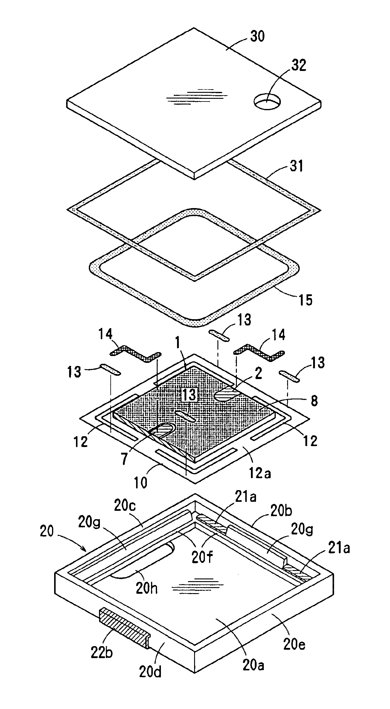
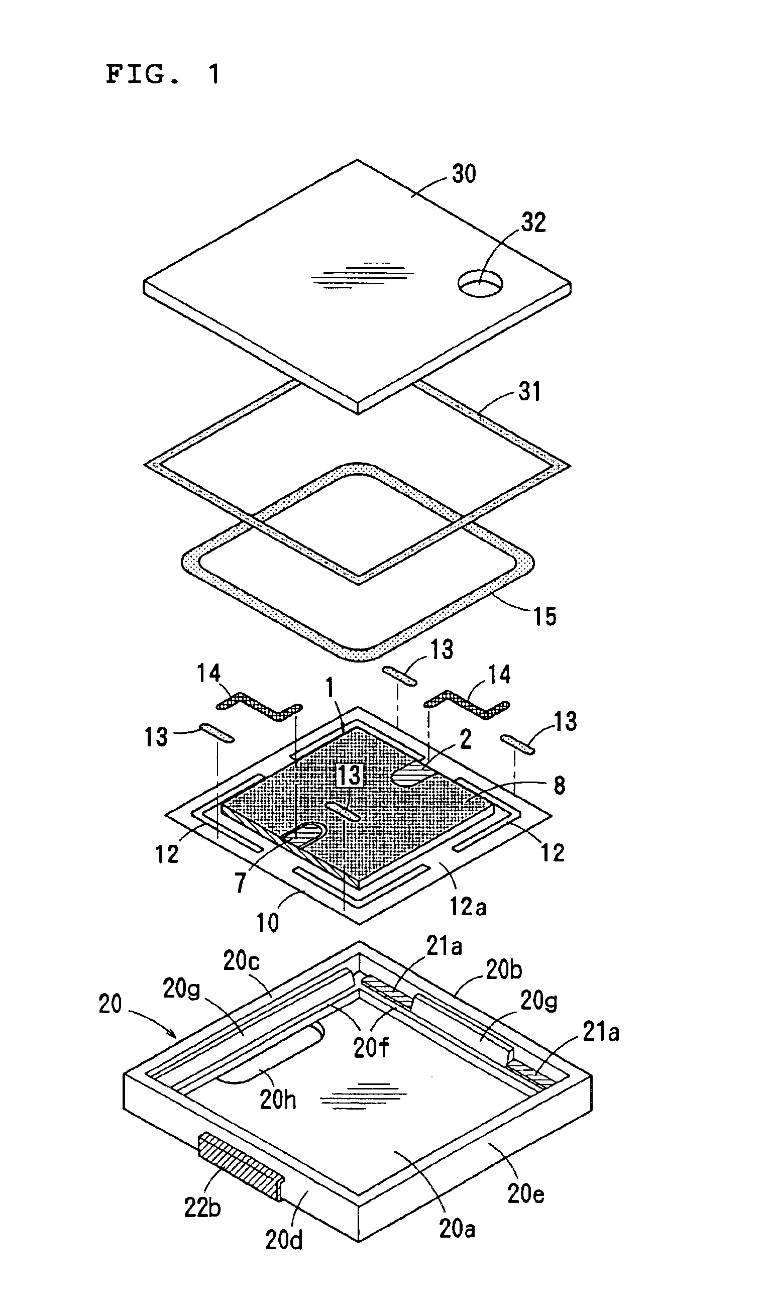
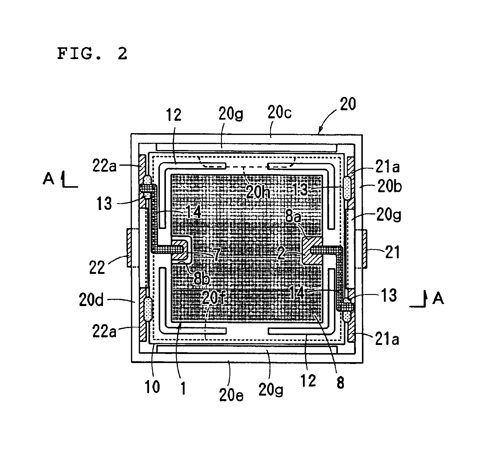
[0057]FIGS. 1 to 7 illustrate a surface-mountable piezoelectric electroacoustic transducer according to a first preferred embodiment of the present invention.

[0058]The electroacoustic transducer according to the present preferred embodiment is capable of playing back a broadband voice having an almost flat sound-pressure characteristic in the human voice band (about 300 Hz to about 3.4 kHz) like a piezoelectric receiver and includes a laminated piezoelectric diaphragm 1, a resin film 10, a casing 20, and a cover 30. The casing 20 and the cover 30 define a housing.

[0059]As shown in FIGS. 6 and 7, the diaphragm 1 is preferably formed by laminating two ceramic layers 1a and 1b and has principal-surface electrodes 2 and 3 formed on top and bottom principal surfaces thereof, and the ceramic layers 1a and 1b have an internal electrode 4 interposed therebetween. The two ceramic layers 1a and 1b are polarized in the same thickness direction as shown by the bold arrows indicated in the figur...


PUM

PropertyMeasurementUnit
Temperatureaaaaaaaaaa
Fractionaaaaaaaaaa
Fractionaaaaaaaaaa

Abstract

A piezoelectric electroacoustic transducer includes a substantially rectangular piezoelectric diaphragm having an internal electrode, a plurality of laminated piezoelectric ceramic layers having the internal electrode interposed between two of the piezoelectric ceramic layers, principal-surface electrodes disposed on top and bottom principal surfaces of the piezoelectric diaphragm, the piezoelectric diaphragm generating surface bending-vibrations in response to application of an alternating signal between the principal-surface electrodes and the internal electrode, a resin film that is larger than the piezoelectric diaphragm and having the piezoelectric diaphragm affixed onto substantially a central portion of a front surface thereof, and a housing having a support for supporting the outer periphery of the resin film. The resin film has heat resistance at least a reflow-soldering temperature and at least one undulated portion bending in the front and rear directions thereof and formed in the outer periphery thereof, and the perimeter of the resin film including the four corners thereof is fixed to the support of the housing by adhesion.

Description

BACKGROUND OF THE INVENTION[0001]1. Field of the Invention[0002]The present invention relates to piezoelectric electroacoustic transducers such as a piezoelectric receiver, a piezoelectric sounder, and a piezoelectric loudspeaker, and more particularly, the present invention relates to a surface-mountable electroacoustic transducer.[0003]2. Description of the Related Art[0004]Conventional electroacoustic transducers have been widely used in electronic apparatuses, household electrical appliances, portable phones, and so forth, to provide a piezoelectric sounder or a piezoelectric receiver generating an audible alarm or an operating sound.[0005]The known electroacoustic transducer has a general structure in which a unimorph piezoelectric diaphragm is formed by affixing a piezoelectric plate onto one surface of a metal plate, the perimeter of the metal plate is fixed inside a casing by adhesion, and the opening of the casing is covered with a cover.[0006]However, since such a diaphrag...

Claims


Application Information

Patent Timeline
IPC IPC(8): H04R17/00
CPCH04R17/00H04R31/003Y10T29/42H04R2307/023
Inventor TAKESHIMA, TETSUOYAMAUCHI, MASAKAZUSUMITA, MANABU
Owner MURATA MFG CO LTD
Why Eureka
Try Eureka