Image forming apparatus for monochromatic and color image formation

a monochromatic and color image technology, applied in the field of image forming apparatus, can solve the problems of high cost, high cost, and high cost, and achieve the effect of enhancing color reproducibility and high image formation speed

Inactive Publication Date: 2005-05-03
SHARP KK
View PDF22 Cites 14 Cited by
  • Summary
  • Abstract
  • Description
  • Claims
  • Application Information

AI Technical Summary

Benefits of technology

[0014]An object of the invention is to provide an image forming apparatus which is capable of supplying image data to each image forming section, in a manner suited for a conveying path which is made shortest so as to achieve the highest image formation speed, in either of two cases: a case of forming any of a monochromatic image, a color image, and a mixed image obtained by combining monochromatic and color images, on only one surface of recording paper; and a case of forming any of the above-mentioned images on both surfaces of the recording paper and also capable of enhancing color reproducibility by ensuring conformity in the relative size between monochromatic and color images formed onto recording paper having been deformed while passing through at least one of the forming sections.

Problems solved by technology

The negative side is that, since a developer in use, which is obtained by mixing pigment or dye into powder of thermoplastic resin, is transferred onto recording paper and is then fixed thereon by heating, a change of hue is likely to occur due to the influence of the transparency of the resin powder and to a temperature rise occurring during the fixation, resulting in poor color reproducibility.
The negative side is that much time needs to be spent in drying the ink and thus speeding-up of operation cannot be achieved, and that the running cost is sharply increased because of the use of relatively expensive ink.
However, in the conventional image forming apparatus employing a developer-system image forming section and an ink-system image forming section in combination, it has proved impossible to make sufficiently short the paper conveying path running through the developer-system image forming section and the ink-system image forming section, in consideration of the difference in image forming speed between the developer system and the ink system.
Consequently, the apparatus as a whole cannot be kept satisfactorily compact.
As a result, the recording paper suffers from slack or is pulled forward and backward, causing paper jamming or tearing.
This leads to unevenness in the degree of influence exerted upon the recording paper as a result of heating and pressurizing performed by the fixation section, giving rise to lack of uniformity in the image forming condition.
Moreover, the conventional image forming apparatus employing a developer-system image forming section and an ink-system image forming section in combination pays no regard to the case of forming images on both surfaces of recording paper, and thus the following problem is posed.
This leads to poor color reproducibility.
In this respect, since the conventional image forming apparatus pays no regard to adjustment of quantity of image data, there appears disconformity in the relative size between monochromatic and color images formed onto recording paper.
This leads to poor color reproducibility.

Method used


Image

  • Image forming apparatus for monochromatic and color image formation
  • Image forming apparatus for monochromatic and color image formation
  • Image forming apparatus for monochromatic and color image formation

Examples


Embodiment Construction

[0075]Now referring to the drawings, preferred embodiments of the invention are described below.

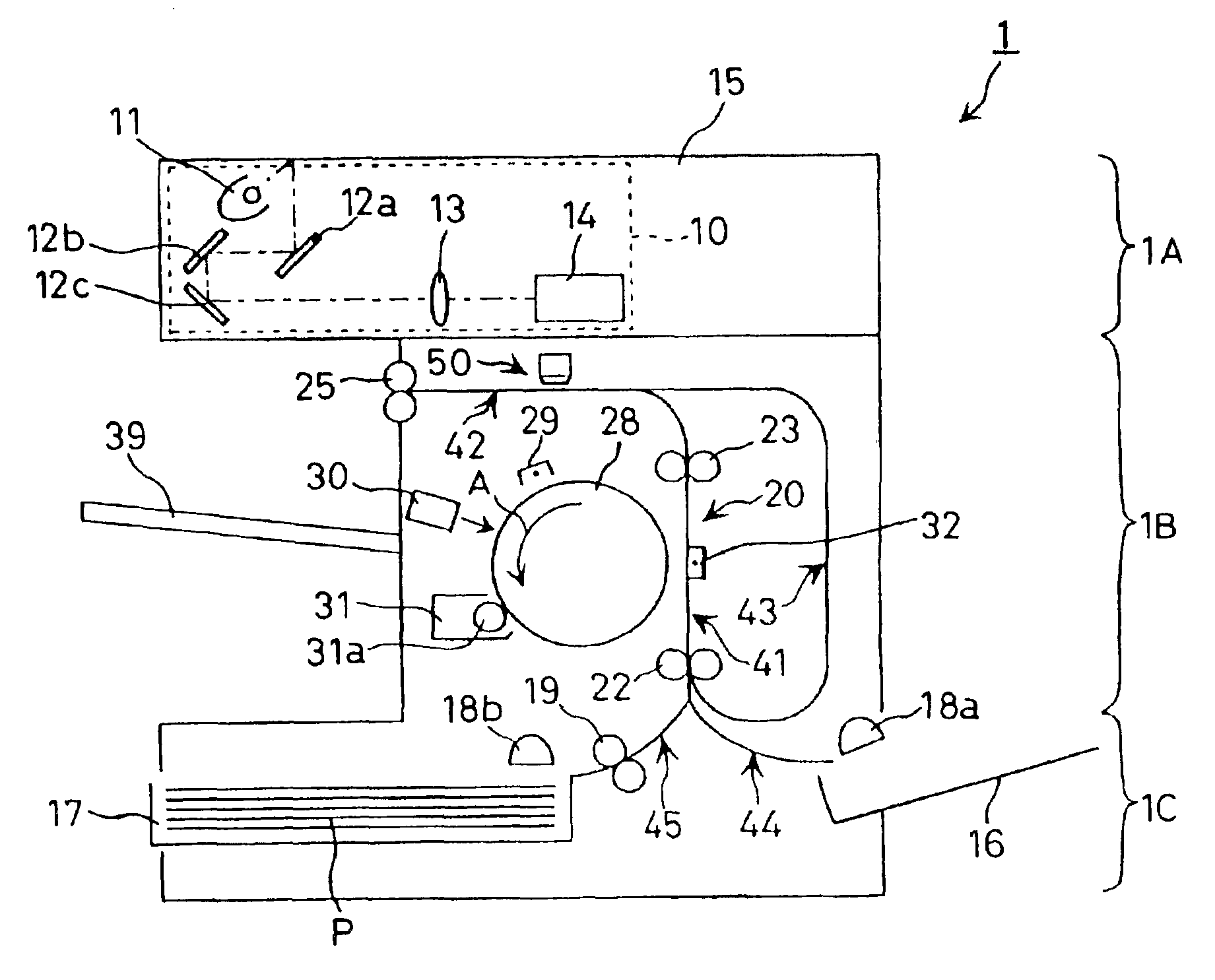
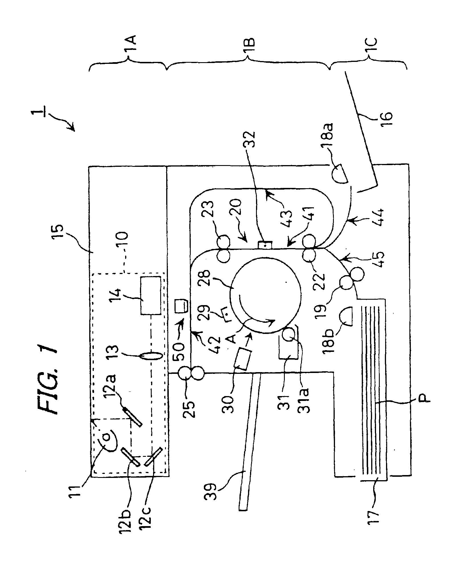
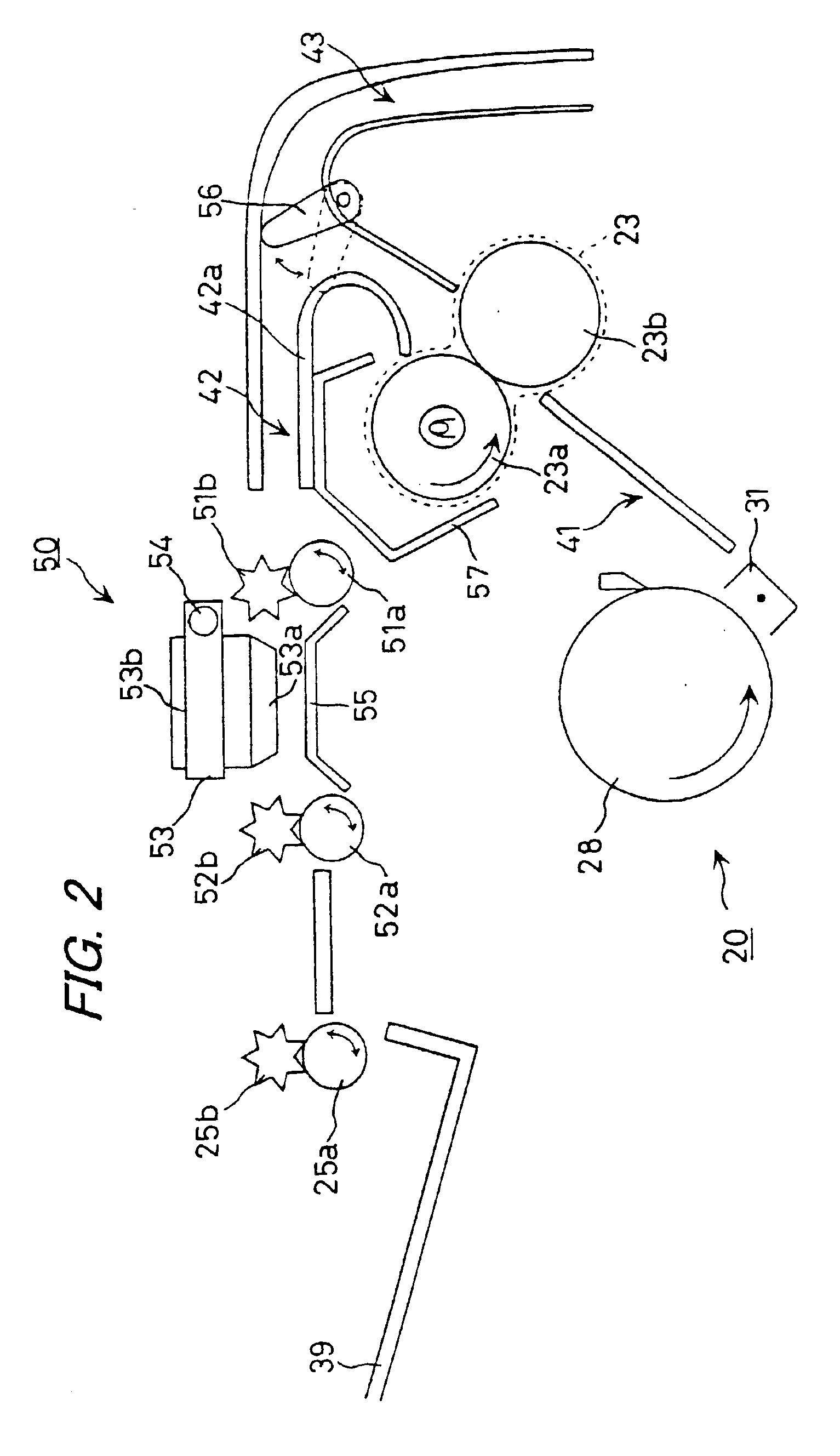
[0076]Hereinafter, a description will be given as to an image forming apparatus according to an embodiment of the invention. Here, a digital copier is taken as an example. FIG. 1 is a schematic view showing the structure of the digital copier according to the embodiment of the invention. FIG. 2 is a view showing the structure of the periphery of the second image forming section provided in the printer unit of the digital copier. The digital copier 1 is designed to have in its upper part a scanner unit 1A, have in its middle part the printer unit 1B, and have in its lower part a paper supply unit 1C, so as to take a substantially U-shaped configuration.

[0077]The scanner unit 1A is provided with an original stand 15 made of transparent hard glass and a scanner optical system 10 located below the original stand 15. The original stand 15 is so arranged as to be exposed at the top surface of t...


PUM


Abstract

An image forming apparatus is provided which includes a first image forming section for performing image formation based on monochromatic image data, and a second image forming section for performing image formation based on color image data. The first and second image forming sections are arranged in mutually different positions along a path for conveying recording paper. The image forming apparatus further includes an image processing section for outputting monochromatic image data and color image data, which have undergone image processing, to the first image forming section and the second image forming section respectively, at individual timings for forming images an either one or both sides of the recording paper.

Description

BACKGROUND OF THE INVENTION[0001]1. Field of the Invention[0002]The present invention relates to an image forming apparatus employing two different image forming sections in combination, of which one is designed for performing monochromatic image formation based on a method using a developer, such as an electrophotographic system, and the other is designed for performing color image formation based on a method using ink, such as an ink-jet system.[0003]2. Description of the Related Art[0004]Conventionally, as image forming methods for forming a color image, there have been known a method using a developer, such as an electrophotographic system, and a method using ink, such as an ink-jet system. These two conventional systems each have advantage and disadvantage. Regarding the electrophotographic system, the positive side is that speeding-up of image formation can be achieved by forcibly fixing a developer onto a paper sheet through application of heat and pressure, and that the runn...

Claims


Application Information

Patent Timeline
Patent Type & Authority Patents(United States)
IPC IPC(8): B41J3/54G03G15/00G03G15/22B41J29/38G03G15/01G03G21/00G03G21/14H04N1/23H04N1/29H04N1/393H04N1/46H04N1/60
CPCB41J3/546G03G15/04072G03G15/221
Inventor MORIMOTO, KENICHI
Owner SHARP KK
Why Eureka
Try Eureka