Graphical automated machine control and metrology

a technology of automated machine control and metrology, applied in the field of graphic systems, can solve the problems of many labor intensive and time-consuming steps, time-consuming and costly methods, and many recording heads that are unnecessary to be destroyed, and achieve the effect of simple and efficien

Inactive Publication Date: 2005-05-03
FEI CO
View PDF14 Cites 95 Cited by
  • Summary
  • Abstract
  • Description
  • Claims
  • Application Information

AI Technical Summary

Benefits of technology

[0007]An object of the invention is to provide a simple, e

Problems solved by technology

This method is time consuming and costly.
Because many recording heads are fabricated on each wafer, cleaving the wafer results in the unnecessary destruction of many recording heads.
Also, many labor intensive and time consuming steps a

Method used


Image

  • Graphical automated machine control and metrology
  • Graphical automated machine control and metrology
  • Graphical automated machine control and metrology

Examples


Embodiment Construction

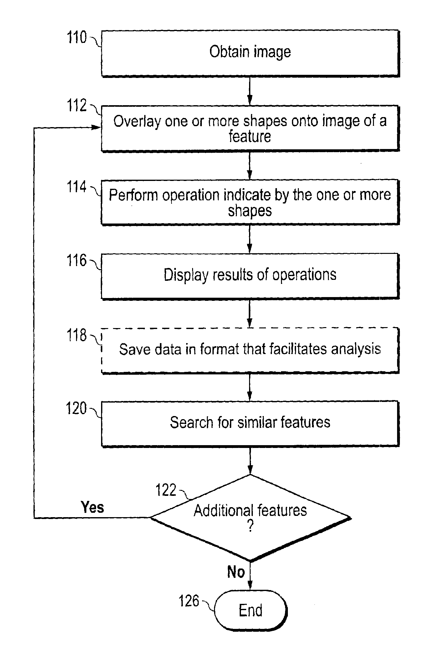
[0026]The invention combines an image of a work piece with operator controllable, computer-generated graphics, some of the graphics having operations associated therewith such that the graphics specify an operation on the image or on the work piece of which the image is formed.

[0027]In some implementations, the invention combines imaging with computer-aided design-type software. For example, one or more images from a charged particle beam microscope are used as a background upon which are superimposed one or more graphics components, such as vector-type graphic components, generated by the computer-aided design software. The scale of the page is automatically set to the scale of the image or images that it contains. The user can then specify operations to be performed on the image or on the work piece that is imaged by manipulating the computer-aided design components.

[0028]The operations can include, for example, moving the stage of a charged particle beam system, milling a specime...


PUM


Abstract

A graphical programming system allows a user to place geometric shapes onto a scaled image, the shape having associated behavior that operates on the image or on the object of which the image is formed. In a preferred embodiment, the shapes are objects in the Visio program by Microsoft Corporation. The shapes are dragged from a stencil onto an image provided by ion beam or electron microscope image. The shape invokes software or hardware to locate and measure features on the image or to perform operations, such as ion beam milling, on the object that is imaged.

Description

[0001]This application claims priority from U.S. Provisional Pat. App. 60 / 314,687, filed Aug. 23, 2001, which is hereby incorporated by reference.TECHNICAL FIELD OF THE INVENTION[0002]The present invention relates to a graphical system for automated control of image-based operation.BACKGROUND OF THE INVENTION[0003]To determine the characteristics of certain objects, particularly characteristics that require instruments to observe, it is often necessary to obtain images of the object and then to perform measurements on the image. For example, microscopic structures are often viewed and measured using electron microscope images. Similarly, astronomical images from telescopes are used to facilitate measurement of large, but distant astronomical objects.[0004]“Microfabrication” is the fabrication of extremely small structures. Microfabrication processes are used, for example, to produce structures in integrated circuits, to build magnetic heads for reading and writing to magnetic media,...

Claims


Application Information

Patent Timeline
IPC IPC(8): G06F3/00G06F19/00G09G5/00G01Q60/00G06T1/00G05B19/4093G06T3/00
CPCG05B19/40933H01J37/28H01J37/3056H01J37/3023G01N1/286G05B2219/36314G05B2219/36317G05B2219/36325H01J2237/31749H01J2237/2813H01J2237/30416H01J2237/30483H01J2237/31713H01J2237/31745Y02P90/02
Inventor TASKER, DAVID J.LEZEC, HENRI J.HEAD, DAVID A.
Owner FEI CO
Why Eureka
Try Eureka