Method and apparatus for monitoring turbine parameters of turbine/alternator on common shaft

a technology of turbines and parameters, applied in the direction of motor/generator/converter stoppers, turbine/propulsion engine ignition, dynamo-electric converter control, etc., can solve the problems of complex prior art systems and difficult implementation

Inactive Publication Date: 2005-05-10
WELLS FARGO BANK NAT ASSOC
View PDF21 Cites 25 Cited by
  • Summary
  • Abstract
  • Description
  • Claims
  • Application Information

AI Technical Summary

Benefits of technology

[0004]In accordance with the present invention, an alternator having a permanent magnet rotor is connected to the main turbine rotor making possible both starting of the turbine as well as generation of electrical power. The electrical system described herein allows the rotor to operate at various speeds with an output frequency and voltage unrelated to rotor speed. The electrical system incorporates a unique inverter which yields the appropriate voltage and frequency in both the start-up mode of operation as well as in the power generation mode of operation.

Problems solved by technology

These prior art systems are complex and difficult to implement.

Method used


Image

  • Method and apparatus for monitoring turbine parameters of turbine/alternator on common shaft
  • Method and apparatus for monitoring turbine parameters of turbine/alternator on common shaft
  • Method and apparatus for monitoring turbine parameters of turbine/alternator on common shaft

Examples


Embodiment Construction

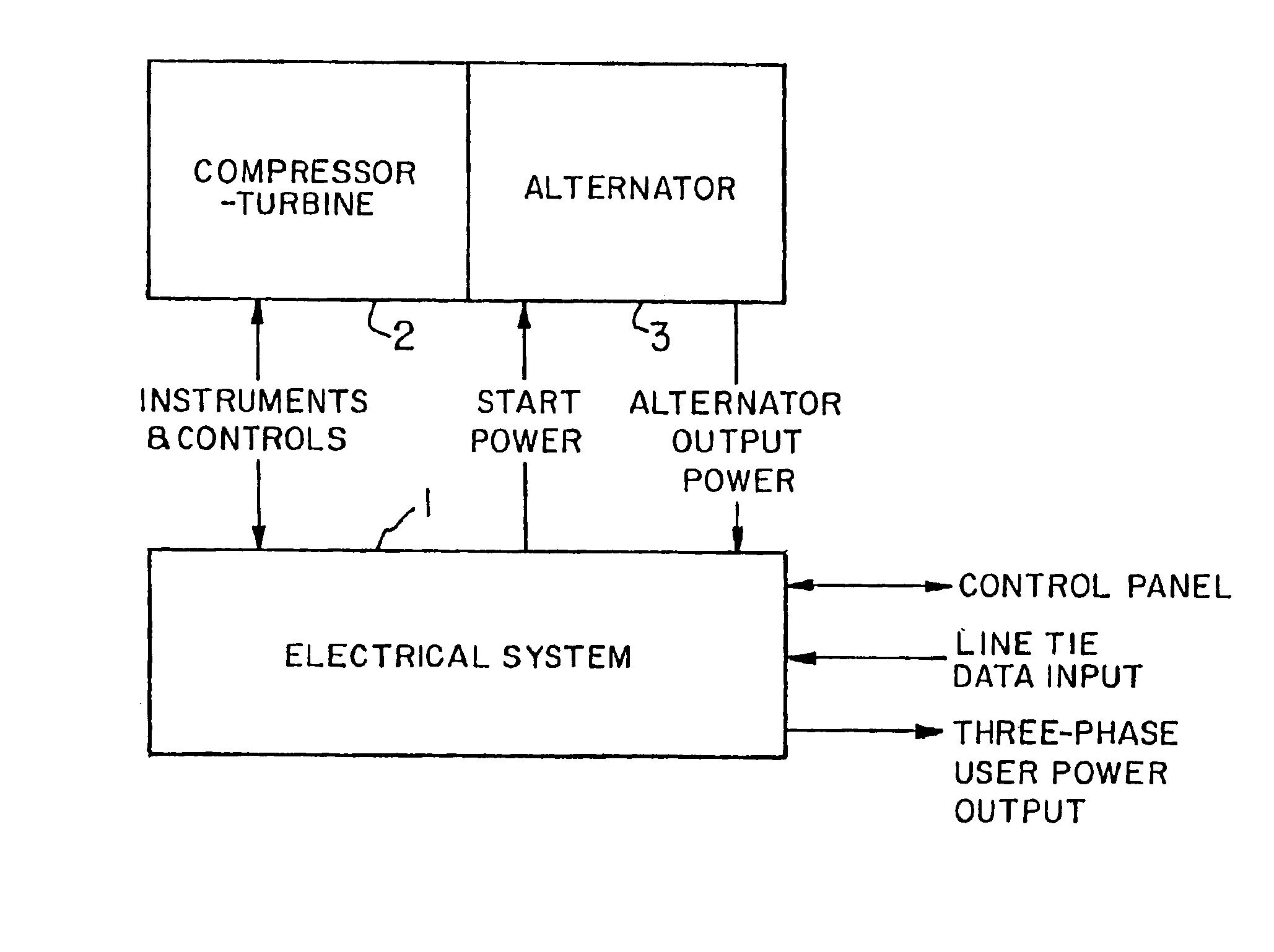
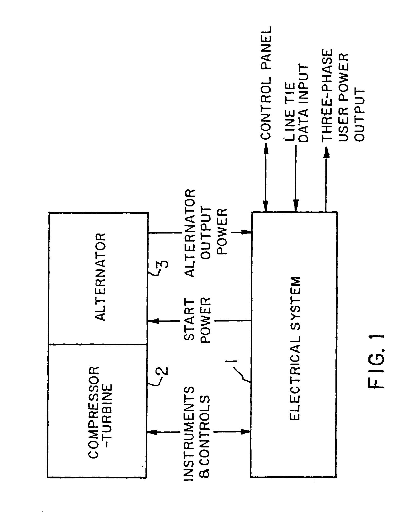
[0019]FIG. 1 illustrates the relation between the electrical control system 1, according to this invention, and the power generation system comprising a gas turbine 2 and an alternator 3. The alternator armature is mounted on a shaft common with the turbine shaft. The electrical control system interacts with the power generation system to provide start-up power, engine control, signal processing, battery charging, user interfaces, as well as power conversion and control for generating user power. Both stand-alone and line tie operations are facilitated.

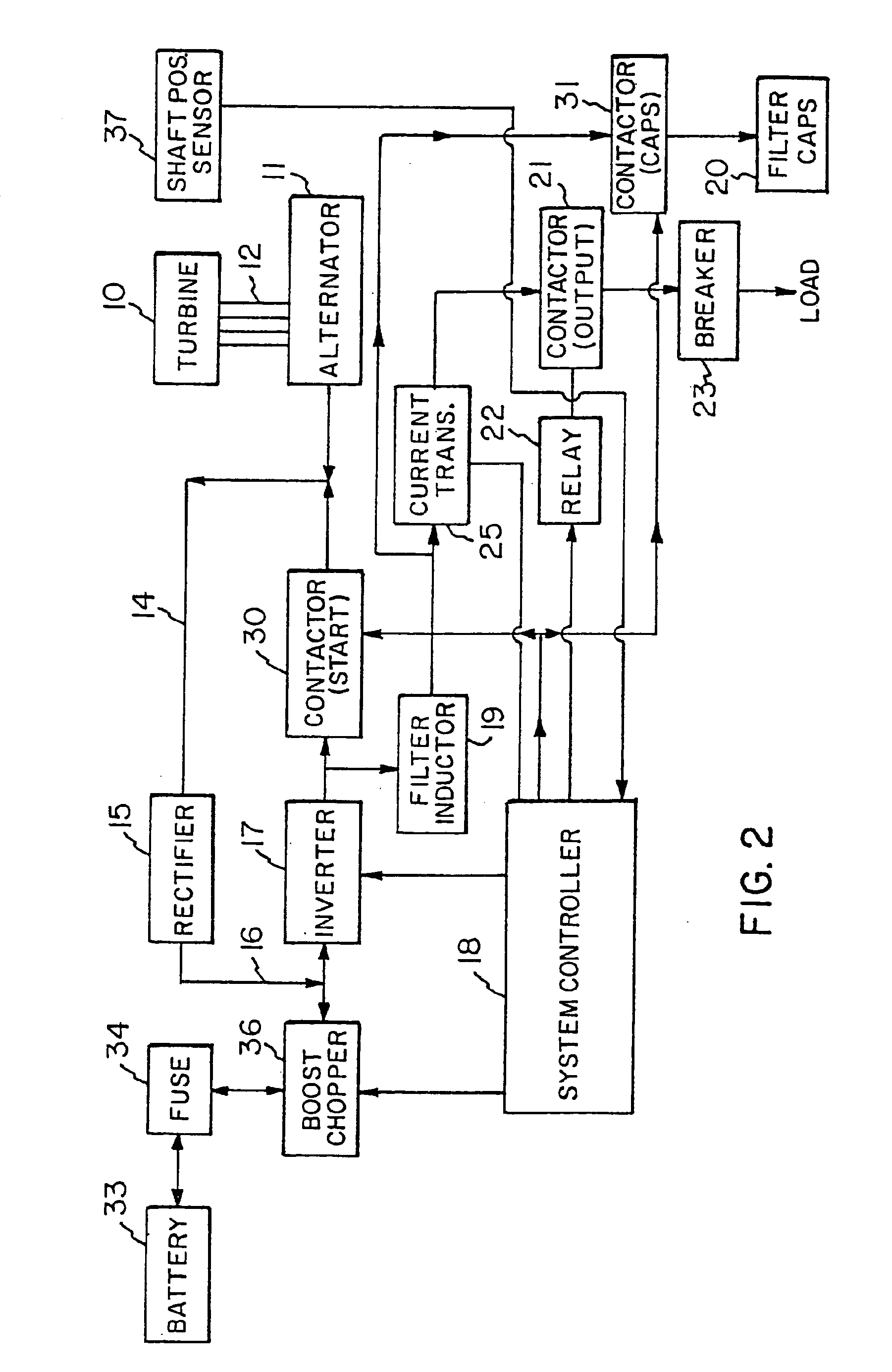
[0020]Referring now to FIG. 2, the general arrangement of the electrical power circuits for a turbine generator, according to this invention, is depicted. A turbine 10 is connected to a permanent magnet (rare earth samarium-cobalt) alternator 11 by a common shaft 12. The stator is manufactured using a stack of high quality, low loss, electric sheet steel laminations. This stack contains a three-phase distributed winding in twelve stat...


PUM


Abstract

An electrical system and apparatus for a turbine / alternator comprising a gas driven turbine and a permanent magnet alternator rotating on a common shaft includes an inverter circuit connectable either to an output circuit or the stator winding of the alternator. A control circuit during a start-up mode switches the inverter circuit to the stator winding of the alternator and during a power out mode switches the inverter circuit to the output circuit. The operating parameters of the turbine are monitored during start-up and / or the power out mode.

Description

CROSS REFERENCE TO RELATED APPLICATIONS[0001]This application is a division of U.S. patent application Ser. No. 10 / 446,386 filed on May. 28, 2003 which is a continuation of U.S. patent application Ser. No. 09 / 840,572, filed Apr. 23, 2001 now U.S. Pat. No. 6,605,928, which is a continuation of U.S. application Ser. No. 09 / 319,390, filed Jun. 1, 1999, which is the United States national phase of International Application No. PCT / US97 / 22405, filed Dec. 3, 1997 which designated, inter alia, the United States, and which claims the benefit of U.S. Provisional Application No. 60 / 032,149, filed Dec. 3, 1996.BACKGROUND OF THE INVENTION[0002]Gas turbines must be driven to rotate at a starting speed by auxiliary means prior to fuel injection and ignition and self-sustained operation. In the past, for example, gear box systems driven by auxiliary electric or compressed air motors have been used to rotate the turbine to starting speed. “Air” impingement starting systems have also been used with ...

Claims


Application Information

Patent Timeline
Patent Type & Authority Patents(United States)
IPC IPC(8): F01D15/00F01D15/10F02C7/26F02C7/275F02C7/268F01D19/00F01K13/02F02N11/04H02P9/04H02P9/08H02P9/44H02P9/48
CPCF01D15/10F02C7/26F02C7/268F02C7/275H02P9/48F02N11/04Y10T24/201Y02T50/672Y10T24/202Y02T50/60H02P9/04
Inventor GUPTA, SURESH C.BURNHAM, DOUGLAS R.TEETS, J. MICHAELTEETS, JON W.
Owner WELLS FARGO BANK NAT ASSOC
Why Eureka
Try Eureka