Edge synchronized phase-locked loop circuit

a phase-locked loop and loop circuit technology, applied in the direction of pulse automatic control, oscillator generator, amplitude demodulation, etc., can solve the problems of circuit instability, difficulty in creating test vectors, circuits that cannot predict the phase of output signals, etc., and achieve the effect of producing a single double-length clock phas

Inactive Publication Date: 2005-05-10
ZORAN CORPORATION
View PDF5 Cites 20 Cited by
  • Summary
  • Abstract
  • Description
  • Claims
  • Application Information

AI Technical Summary

Benefits of technology

[0005]The present invention provides a phase-locked loop circuit for synchronizing an edge of an output signal with an edge of an input signal. The illustrative embodiment of the present invention detects an edge of an input clock signal, and a corresponding edge on an output signal. If the output signal edge is out of phase with the input clock edge, the circuit shifts the output signal by 180 degrees to effectively produce a single double-length clock phase. The present invention provides a synchronized phase-locked loop circuit that provides predictable PLL output phase synchronization with an input clock.

Problems solved by technology

A problem with conventional phase-locked loop circuits is that the conventional phase-locked loop circuits cannot predict the phase of an output signal without an extended observation.
A phase-locked loop produces an edge in an output signal when an input signal produces an edge, but the circuit is unpredictable as to whether the corresponding output edge is rising or falling.
The unpredictable timing of a phase-locked loop circuit causes difficulty in creating test vectors for automated production testing of an integrated circuit that uses PLL for clocking.

Method used


Image

  • Edge synchronized phase-locked loop circuit
  • Edge synchronized phase-locked loop circuit
  • Edge synchronized phase-locked loop circuit

Examples


Embodiment Construction

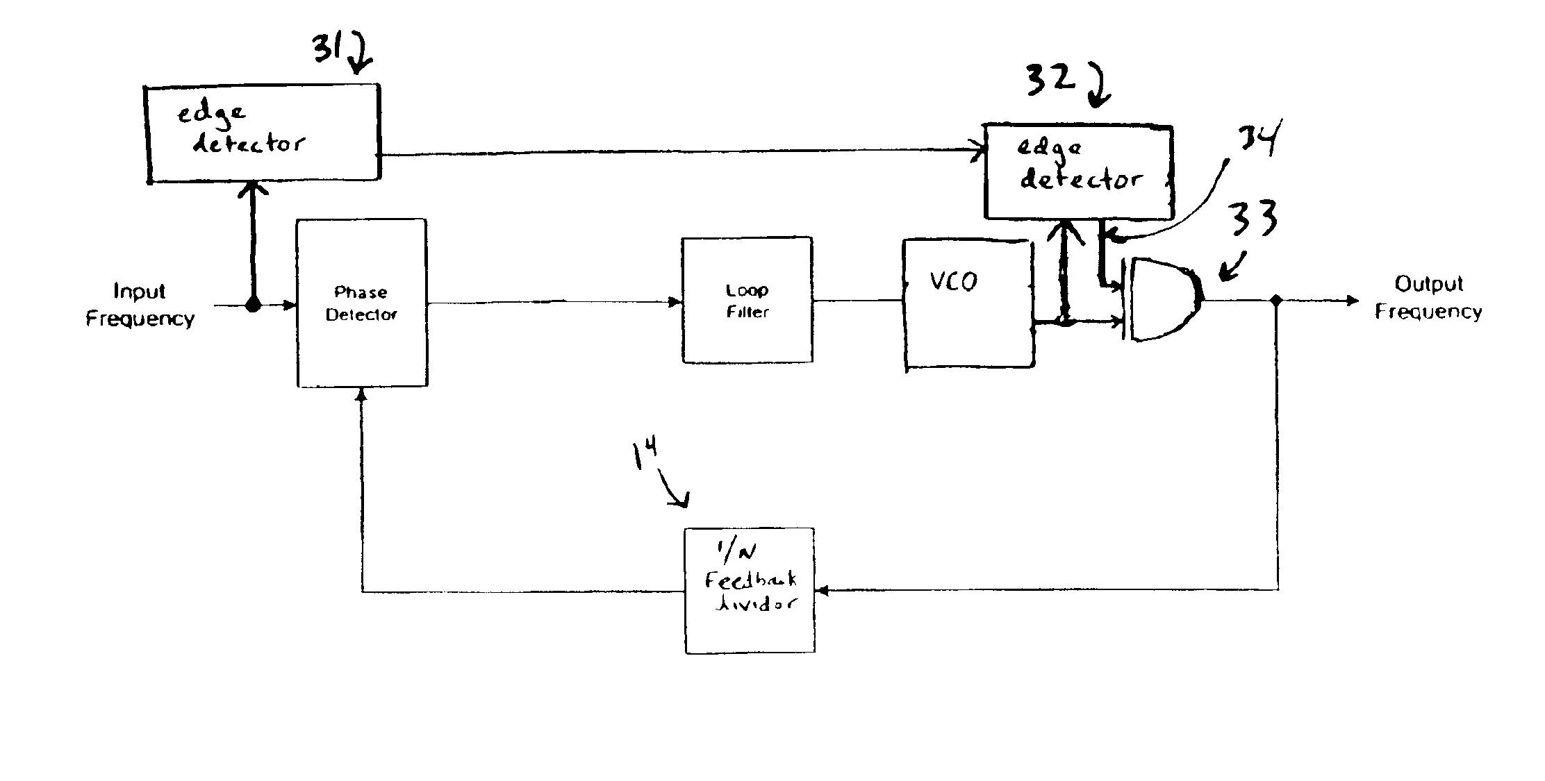
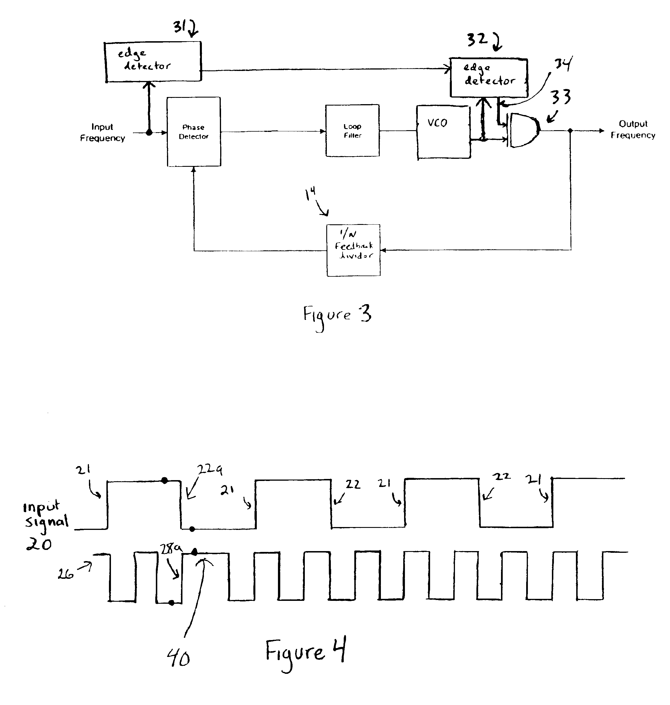
[0013]The illustrative embodiment of the present invention provides a synchronized phase-locked loop circuit that provides predictable output phase synchronization with an input clock. The illustrative embodiment will be described below relative to an illustrative embodiment. Those skilled in the art will appreciate that the present invention is not limited to the illustrative embodiment and may be implemented in a variety of applications.

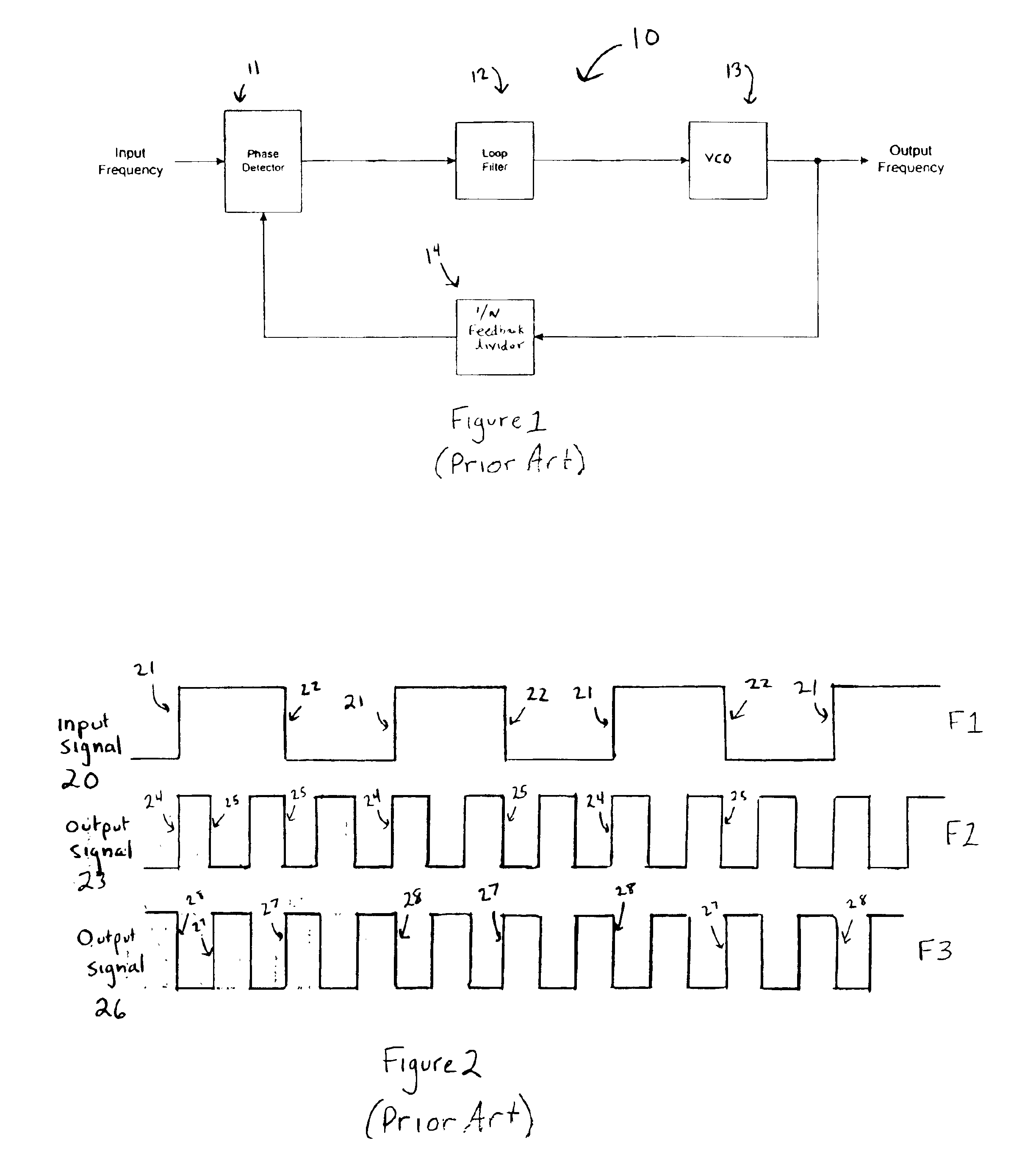
[0014]FIG. 1 illustrates a conventional phase-locked loop circuit. The components of the circuit 10 include a phase detector 11, a loop filter 12, a voltage controlled oscillator (VCO) 13, and a feedback divider 14. The VCO is an oscillator having an output frequency that varies with the applied direct current control voltage. When no voltage is applied to the VCO 13, the VCO oscillates at a predetermined default frequency. A portion of the output frequency signal from the VCO 13 is fed back to the error detector, via the frequency divider 14. The ...


PUM


Abstract

A phase-locked loop circuit for synchronizing an edge of an output signal with an edge of an input signal. The circuit detects an edge of an input clock signal, and a corresponding edge on an output signal. If the output signal edge is out of phase with the input clock edge, the circuit shifts the output signal by 180 degrees to effectively produce a single double-length clock phase. The synchronized phase-locked loop circuit provides predictable phase-locked loop output phase synchronization with an input clock.

Description

FIELD OF THE INVENTION[0001]The present invention relates to phase-locked loop circuits. More particularly, the present relates to a phase-locked loop circuit that multiplies the external clock frequency of a circuit for internal use.BACKGROUND OF THE INVENTION[0002]A phase-locked loop is an electronic circuit that controls an oscillator in order to lock the phase of an output signal to the phase of a reference signal. Generally, a phase-locked loop (PLL) feedback system includes a voltage-controlled oscillator and a phase comparator. The oscillator frequency (or phase) accurately tracks the frequency of an input signal, or an integer multiple of the frequency of the input signal.[0003]A phase-locked loop circuit can be used to generate a stable high frequency output signal from a fixed low-frequency signal. The phase-locked loop circuit generates an output signal that is a multiple of the input signal by using a frequency divider in the feedback stage of the loop. The frequency div...

Claims


Application Information

Patent Timeline
Patent Type & Authority Patents(United States)
IPC IPC(8): H03L7/081H03L7/08H03L7/183H03L7/16
CPCH03L7/183H03L7/081
Inventor ROCHOW, GREGOR BENEDIKT
Owner ZORAN CORPORATION
Why Eureka
Try Eureka