Method and apparatus for geolocating a wireless communications device

a wireless communication and geographic position technology, applied in direction finders using radio waves, wireless commuication services, instruments, etc., can solve the problems of inability to provide location information directly to emergency services personnel, communication device users may be in unfamiliar territory, and inability to use calling telephone numbers as positioning aids, etc., to avoid computation time, high signal-to-noise ratio, computationally simple and robust

Inactive Publication Date: 2005-05-10
HALL CHRISTOPHER J +2
View PDF39 Cites 60 Cited by
  • Summary
  • Abstract
  • Description
  • Claims
  • Application Information

AI Technical Summary

Benefits of technology

[0020]The frequency domain approach of the present invention avoids certain disadvantages of the prior art time-based cross-correlation technique discussed above, and offers unique advantages, such as avoiding the computation time required to form the cross-correlation function and to then locate the function peak. The frequency domain approach also permits the use of frequency domain filtering to select only those frequency components having a relatively high signal-to-noise ratio for determining the phase versus frequency line, as described above, from which the TDOA is determined. Also, in one embodiment the TDOA frequency domain approach exploits the computational efficiency of the fast Fourier transform (FFT) to transform the time domain signal to the frequency domain.
[0021]The method of determining the TDOA according to the present invention is computationally simple and robust. Advantageously, the method can utilize the FFT algorithm since the calculations are done in the frequency domain. The robustness is further enhanced by two filtering processes. The first is the aforementioned frequency domain window filter wherein the high signal-to-noise components (or components selected based on a different signal quality metric) are selected for determining the line and the remaining components are either not considered or less heavily weighted. The second filter process is the regression analysis to find the best fit line, as will be discussed further below.
[0022]The techniques of the present invention can be employed in TDMA and FDMA cellular systems. Although the teachings can also be employed to determine the TDOA in a CDMA-based cellular system, conventional CDMA signal processing at the receiving site inherently determines the signal time of arrival, from which the time difference of arrival of a signal at two receiving sites can be easily determined.

Problems solved by technology
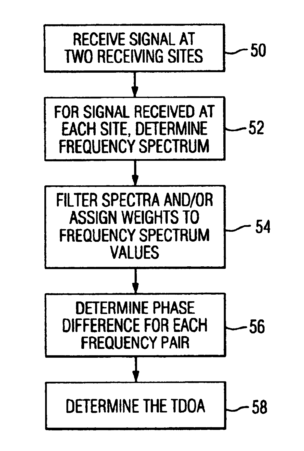
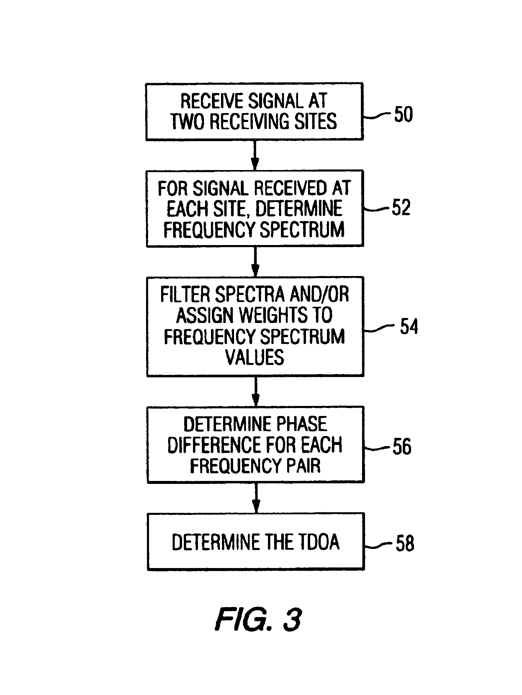
A problem with responding to a request for emergency assistance from a wireless communications device is the inability to use the calling telephone number as an aid to position location.
Also, a wireless communications device user may be in unfamiliar territory and therefore unable to provide location information directly to the emergency services personnel.
This lack of information regarding the caller's location hampers and delays efforts to provide emergency assistance to the caller.
These signal differences can impact the results obtained from the cross-correlation technique described above, making the function peak difficult to locate or shifting the peak from the true TDOA value.
With only two receiving stations using a TDOA method, it is generally not possible to determine a precise location for a target unit, but rather only a locus of points along a curve, such as the curve 6.
In this search process, there can be some difficulty in accurately determining the peak's location because the peak is unlikely to fall directly on a time sample.
Alternatively, the cross-correlation function can be over sampled during the peak search process, but this is accomplished at the expense of increased computational overhead and time.

Method used


Image

  • Method and apparatus for geolocating a wireless communications device
  • Method and apparatus for geolocating a wireless communications device
  • Method and apparatus for geolocating a wireless communications device

Examples


Embodiment Construction

[0030]Before describing in detail the particular method and apparatus for locating wireless communications devices in accordance with the present invention, it should be observed that the present invention resides primarily in a novel combination of hardware elements and software elements related to a method and apparatus for locating wireless communications devices. Accordingly, the hardware and software elements have been represented by conventional elements in the drawings, showing only those specific details that are pertinent to the present invention, so as not to obscure the disclosure with structural details that will be readily apparent to those skilled in the art having the benefit of the description herein.

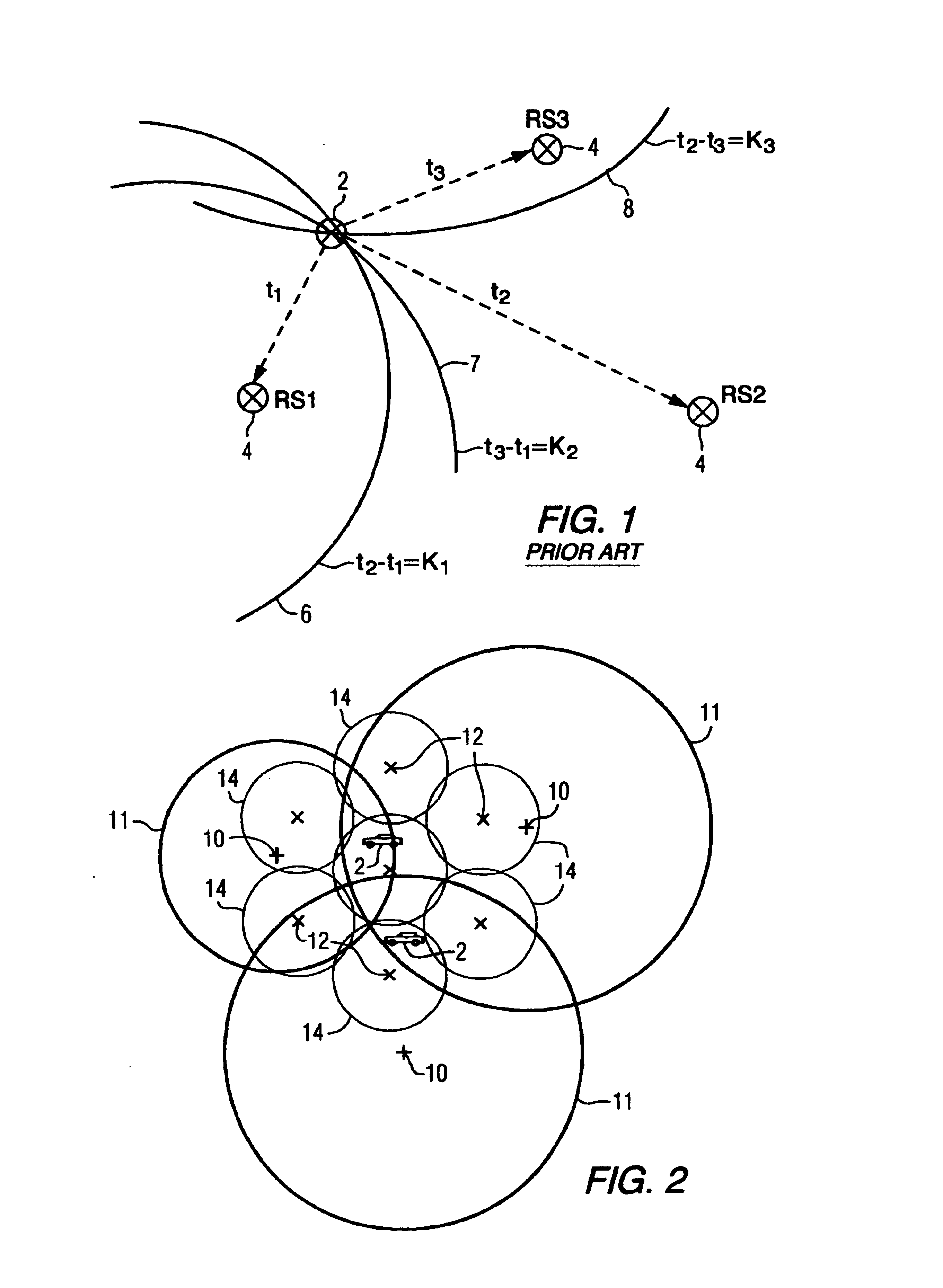
[0031]FIG. 2 shows a map view of a geographical area including three monitoring stations 10 at or near the center of monitoring regions 11, and a plurality of base stations (or receiving sites) 12 at or near the center of a cell coverage areas 14. The monitoring regions ...


PUM


Abstract

The time difference of arrival for a signal received at two or more receiving sites as transmitted from a wireless communications device, is determined by a frequency domain technique. The constituent frequencies of the signals received at the two or more receiving sites are determined, including the phase, or a value representative of the phase, of each frequency component. The phase values for the same frequency are subtracted to yield a phase difference values as a function of frequency. The slope of the function represents the time difference of arrival for the wireless communications device signal as received at the two receiving sites. To determine the mobile location based on the determined time difference of arrival values, a seed or initial location is first assumed for the wireless communications device and the distance difference of arrival (the time difference of arrival multiplied by the speed of light) is calculated. The calculated time difference of arrival is then used to adjust the distance difference of arrival by continuously iterating the position of the wireless communications device until the calculated distance of arrival and the calculated time difference of arrival (as multiplied by the speed of light) are within a predetermined margin.

Description

CROSS REFERENCE TO RELATED APPLICATIONS[0001]This patent application claims the benefit of U.S. provisional patent application No. 60 / 365,104 filed on Mar. 18, 2002, entitled An Alternative Solution to the Problem of Geolocating a Portable Radio Transmitter, and the U.S. provisional application No. 60 / 419,366, filed on Oct. 18, 2002, entitled An Alternate Solution to the Problem of Geolocating a Portable Radio Transmitter.FIELD OF THE INVENTION[0002]This invention relates to methods and apparatuses for determining a geographic position of a portable or mobile wireless communications device, including a mobile cellular telephone, a personal communications device or a location tracking device (referred to generally as a wireless communications device), and in particular to such methods and apparatus using a frequency domain analysis of the received signal to determine the geographic position.BACKGROUND OF THE INVENTION[0003]It is desired to provide emergency service to users of wirele...

Claims


Application Information

Patent Timeline
Patent Type & Authority Patents(United States)
IPC IPC(8): G01S5/06H04Q7/38H04M3/42H04W64/00
CPCG01S5/0205G01S5/06H04W64/00H04M2242/30H04M2207/18
Inventor HALL, CHRISTOPHER J.TURNER, CLAY S.RAY, JIMMY C.
Owner HALL CHRISTOPHER J
Why Eureka
Try Eureka