Optical instrument and process for measurement of samples

a technology of optical instruments and samples, applied in the field of biochemical laboratory instruments, can solve the problems of affecting the accuracy of optical samples, and affecting the accuracy of samples, so as to avoid the attenuation caused by optical fibres, improve the accuracy of measurement, and improve the effect of measurement accuracy

Inactive Publication Date: 2005-05-10
WALLAC
View PDF11 Cites 18 Cited by
  • Summary
  • Abstract
  • Description
  • Claims
  • Application Information

AI Technical Summary

Benefits of technology

[0027]An important advantage of the invention relates to achieving high measurement accuracy. The aperture(s) of the optical module preferably determine the measurement area within the sample. Therefore the measurement area can be separately determined for each optical module. And especially in the two-emission measurement it is possible to determine the measurement areas separately by dimensioning the respective apertures of the optical module for the two simultaneous or successive emissions.
[0028]The changeable optical modules with aperture(s) according to the invention thus allow the dimensioning of the aperture according to a specific measurement. This gives the ability to offer optional functions in measurement equipment. Equipment with a measurement head for one emission measurement can be easily upgraded into equipment, which has a measurem...

Problems solved by technology

There are certain limitations related to the prior art technology.
As the optical modules are manually handled the lenses of the optical module easily become unclean.
This causes attenuatio...

Method used


Image

  • Optical instrument and process for measurement of samples
  • Optical instrument and process for measurement of samples
  • Optical instrument and process for measurement of samples

Examples


first embodiment

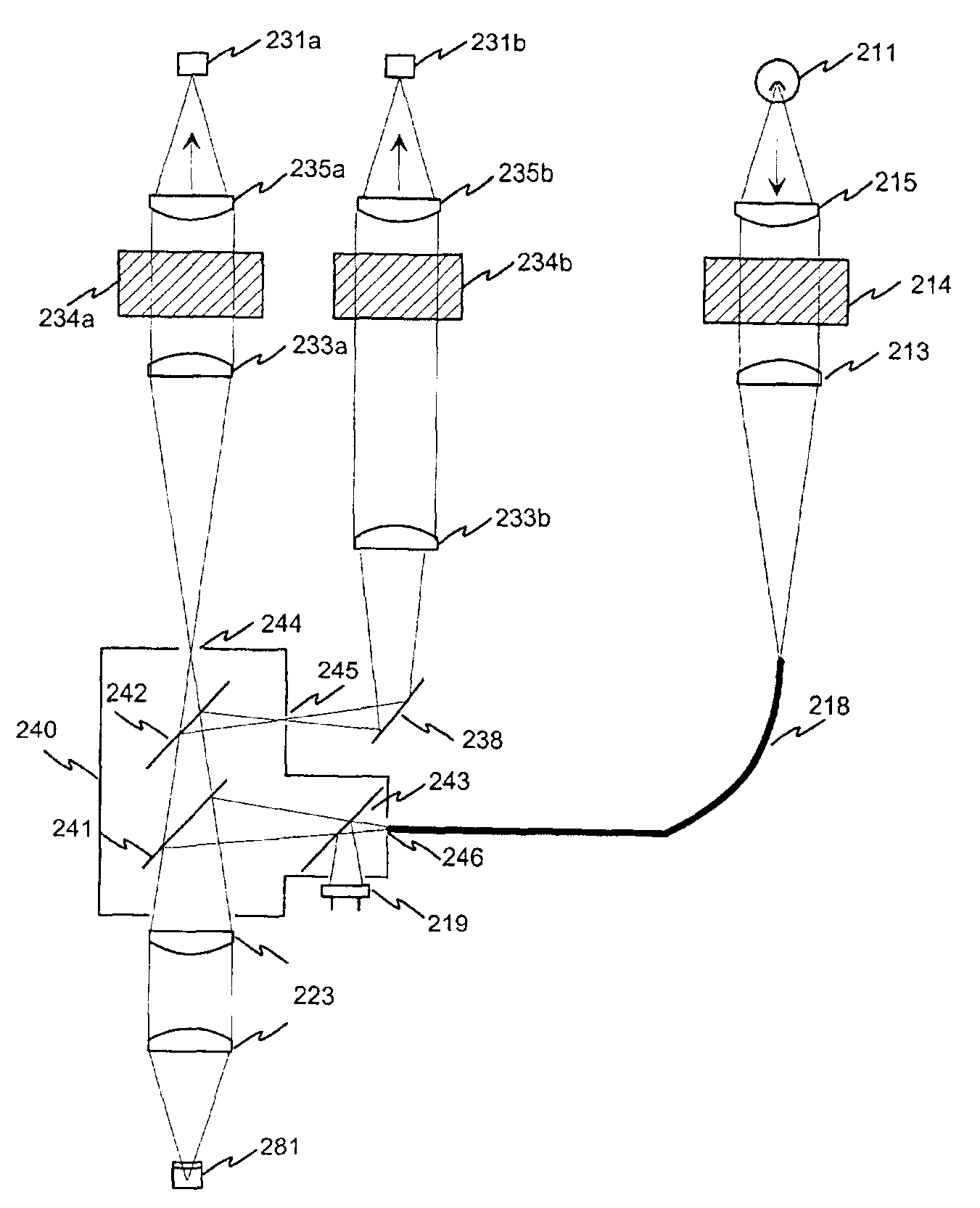
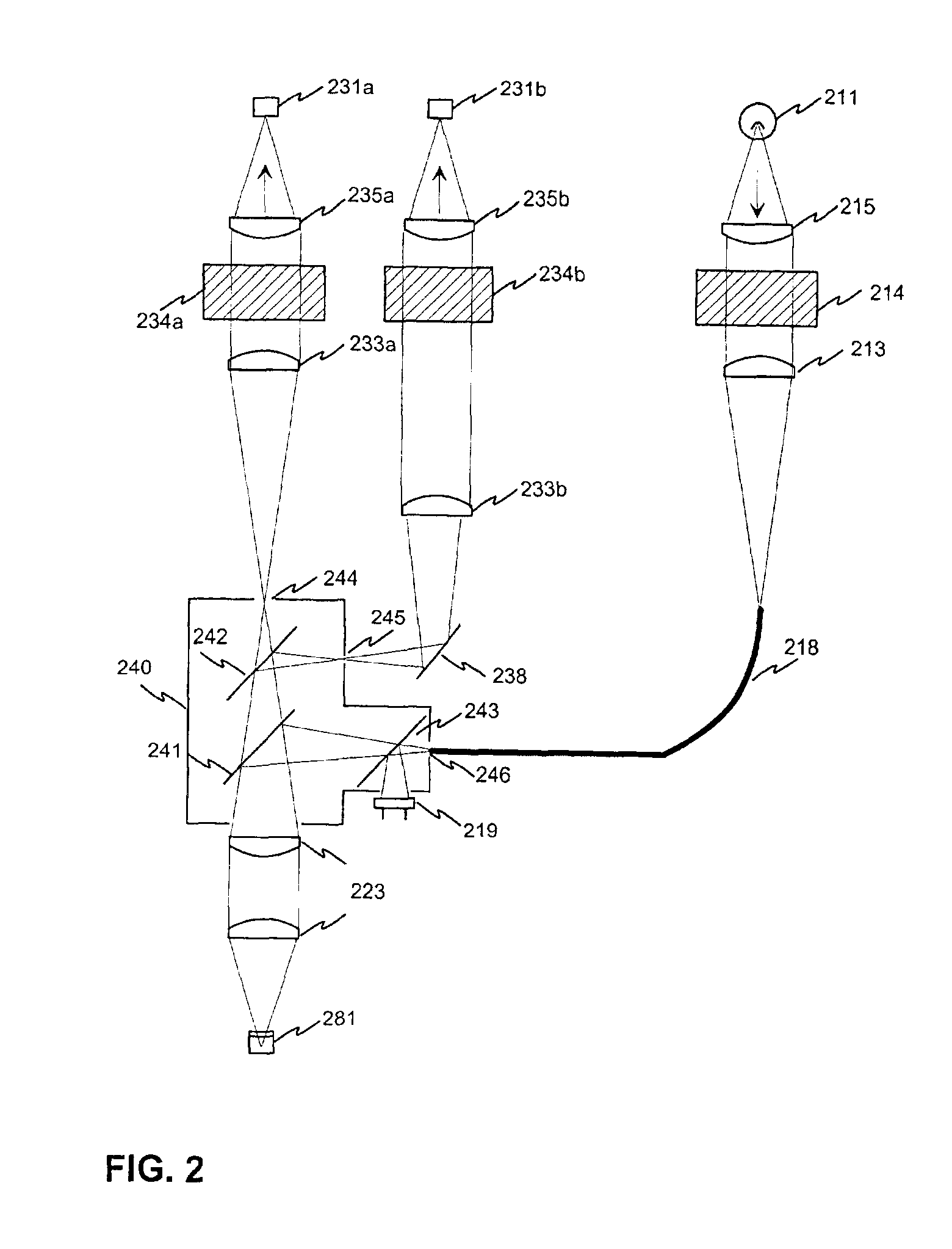
[0078]FIG. 4 illustrates performing a photoluminescence measurement with a measuring instrument according to the present invention. In this embodiment both excitation and detection is made from the above the sample using the top measurement head of the instrument. One of the possible alternative excitation sources 411 gives an excitation pulse, which is guided through an optical system 413 to an optical fibre 418. The optical system may include filters, lenses and mechanical components as was shown in FIG. 3. The excitation beam is mixed in the optical fibre and lead to the optical module 450. The excitation beam is reflected from the mirror 441 and collimated in the optical system 423 into the sample 481 on the sample plate 480 to be measured. The excitation beam provides excitation for two simultaneous measurements.

[0079]The excited sample 481 gives two emissions that are measured with detectors A and B. The emission beams are first collimated in the optical system 423, and the be...

second embodiment

[0082]FIG. 5 illustrates performing a photoluminescence measurement with a measuring instrument according to the present invention. In this embodiment both excitation and detection is made from the below the sample using the bottom measurement head of the instrument. One of the possible alternative excitation sources 511 gives an excitation pulse, which is lead to the optical module of the bottom measurement head with an optical fibre (not shown in the FIG. 5), wherein the excitation beam is mixed. The excitation beam is reflected from the mirror 551 and collimated in the optical system 563 into the sample 581 on the sample plate 580 to be measured. The excitation beam provides excitation for two simultaneous measurements, or alternatively two successive excitations with different wavelengths are made with successive excitation pulses (successive excitation is preferably used only in bottom measurements).

[0083]The excited sample 581 gives two emissions that are measured with detecto...

third embodiment

[0085]FIG. 6 illustrates performing a photoluminescence measurement with a measuring instrument according to the present invention. In this embodiment the excitation is made from the above the sample using the top measurement head, and the detection is made from below the sample using the bottom measurement head of the instrument. One of the possible alternative excitation sources 611 gives an excitation pulse, which is guided through an optical system 613 to an optical fibre 618. The optical system may include filters, lenses and mechanical components as was shown in FIG. 3. The excitation beam is mixed in the optical fibre and lead to the optical module 650. The excitation beam is reflected from the mirror 641 and collimated in the optical system 623 into the sample 681 on the sample plate 680 to be measured. The excitation beam provides excitations for two simultaneous measurements.

[0086]The excited sample 681 gives two emissions that are measured with detectors A and B. The emis...


PUM


Abstract

The present invention relates generally to the field of biochemical laboratory. More particularly the invention relates to the improved and more accurate instrumental features of equipment used as e.g. fluorometers, photometers and luminometers. The object of the invention is achieved by providing an optical measurement instrument where there is an interface (218, 223, 233a, 233b, 238) for a changeable optical module (240), and excitation and/or emission beam is guided through an aperture of the optical module. This allows performing various types of measurements by changing an optical module without a problem lenses becoming unclean due to manual handling of the optical modules. The invention also makes possible to achieve an accurate measurement location and area within a sample.

Description

BACKGROUND OF THE INVENTION[0001]The present invention relates generally to the field of biochemical laboratory instrumentation for different applications of measuring properties of samples on e.g. microtitration plates and corresponding sample supports. More particularly the invention relates to the improved, reliable and more accurate instrumental features of equipment used as e.g. fluorometers, photometers and luminometers.[0002]The routine work and also the research work in analytical biochemical laboratories and in clinical laboratories are often based on different tags or labels coupled on macromolecules under inspection. The typical labels used are different radioactive isotopes, enzymes, different fluorescent molecules and e.g. fluorescent chelates of rare earth metals.[0003]The detection of enzyme labels can be performed by utilizing its natural biochemical function, i.e. to alter the physical properties of molecules. In enzyme immunoassays colourless substances are catalys...

Claims


Application Information

Patent Timeline
IPC IPC(8): G01N21/64G01J3/02G01N21/25G01J3/00
CPCG01J3/02G01J3/0275G01N21/6452G01N2021/6484G01N2021/6471G01N2021/6482G01N21/76
Inventor HARJU, RAIMOISAKSSON, CHRISTER
Owner WALLAC
Why Eureka
Try Eureka