
Optical pickup apparatus and method

Inactive Publication Date: 2005-05-10
INTERSCI
View PDF12 Cites 10 Cited by
  • Summary
  • Abstract
  • Description
  • Claims
  • Application Information

AI Technical Summary

Benefits of technology

[0016]It is also desirable to provide an improved optical pickup device and method which can utilize overlapping diffraction orders, thereby allowing information on an optical disk to be stored more compactly and read more rapidly.
[0017]It is also desirable to provide an improved optical pickup device and method that improves the readout speed at which optical disks are read.SUMMARY OF THE INVENTION
[0018]The present invention applies an electronically reconfigurable grating in an optical pickup, offering higher-data storage density and faster retrieval in the future generations of CD and DVD technology, for audio, video, and computer applications. Currently, optical pickup devices are common to CD and DVD reader technology, however, the present invention is not limited to those devices. All applications of optical pickup devices, current and future, would benefit from the present invention.

Problems solved by technology

The practical applications of this device, however, have been limited so far.
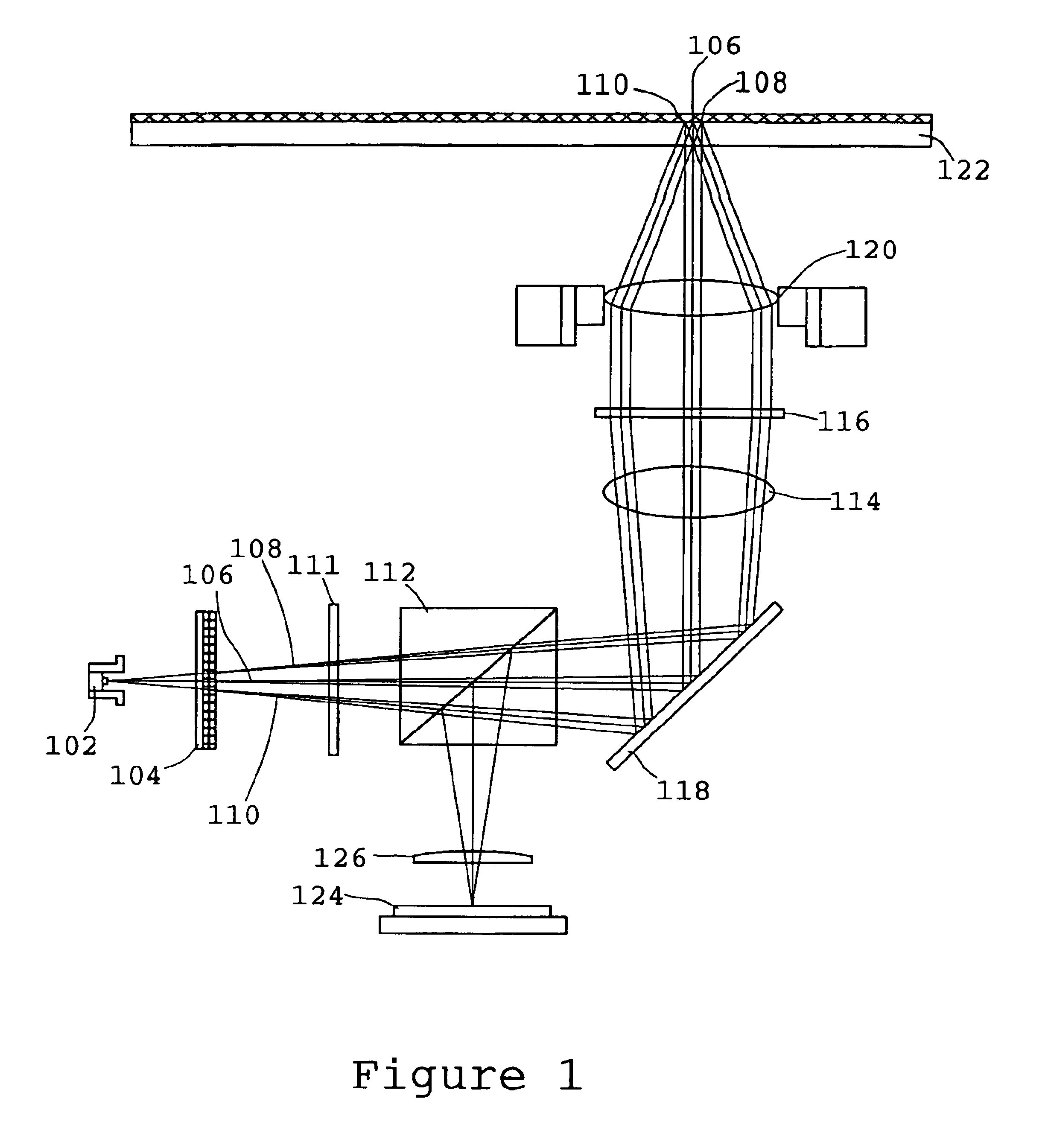
This method of signal detection and processing limits the technology to non-overlapping diffraction limited reflections on the photodetector 128.
Therefore, the prior art technology is limited in optical storage density to a configuration that provides diffraction limited nonoverlapping signals to the photodetector 128.
The prior art technology, as described above, is further limited to using only the diffracted energy in the zero and first orders, in addition to being limited to nonoverlapping reflections on the readout device.

Method used


Image

  • Optical pickup apparatus and method
  • Optical pickup apparatus and method
  • Optical pickup apparatus and method

Examples


Embodiment Construction

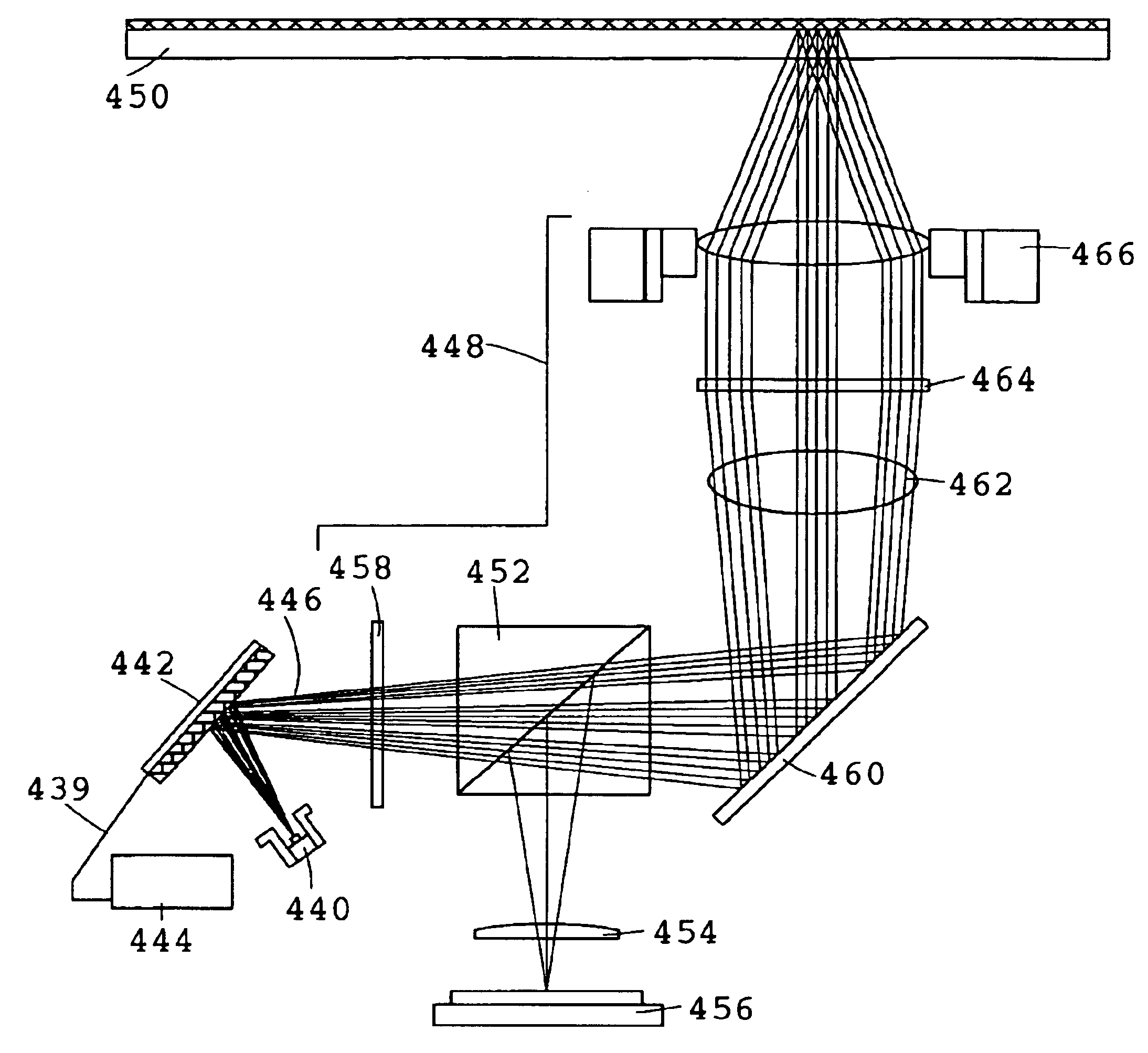
[0038]The present invention is an improved optical pickup device that incorporates an electronically reconfigurable diffraction grating utilizing the zero order and multiple higher diffractive orders. The present invention has new degrees of freedom which can offer many advantages compared to existing optical pickup technology. The main expected useful results are increased data storage density and readout speed. These implementations are not possible using a conventional diffraction grating and can only be realized by the optical pickup device that includes an electronically reconfigurable diffraction grating 442 as described. FIG. 4 shows a schematic of the improved optical pickup device implemented with an optical delivery system similar to the prior art to allow for easy comparison. It is a schematic of the light path of the preferred embodiment of the improved optical pickup device, though variations can be achieved by someone of ordinary skill within the scope of this disclosu...


PUM


Abstract

The present invention provides an improved optical pickup device based on the developing electronically reconfigurable diffraction grating MEMS technology. The improved optical pickup device has applications that include but are not limited to CD and DVD for audio, video and computer technology. The present invention can provide improvements to this current and future technology with higher data storage density and faster retrieval. In a preferred embodiment, the optical pickup apparatus comprises an electronically reconfigurable diffraction grating modulating relative light intensities as among at least two different diffraction orders of light diffracted by the electronically reconfigurable diffraction grating; focusing optics for focusing the light diffracted by the electronically reconfigurable diffraction grating into diffractive spots corresponding with each of the diffraction orders and onto an optical storage medium, which light is then reflected by the optical storage medium; and a detector for detecting the light reflected by the optical storage medium and striking said detector.

Description

CROSS-REFERENCE TO RELATED APPLICATION[0001]This application claims the benefit of U.S. Provisional Application No. 60,149,856, filed Aug. 19, 1999.FIELD OF THE INVENTION[0002]This invention relates to the field of optical pickup devices, and particularly to electronically-controlled optical pickup devices.BACKGROUND OF THE INVENTION[0003]Various configurations and implementations of electronically reconfigurable diffraction gratings fabricated using MEMS technology are disclosed, for example, in U.S. Pat. No. 5,841,579 by Bloom, et al.; U.S. Pat. No. 5,757,536 by Ricco, et al.; and U.S. Pat. No. 5,999,319 by Castracane. These MEMS-based electronically reconfigurable diffraction gratings offer new and unique degrees of freedom in controlling diffraction of light from a grating, bringing qualitatively new potential to this centuries-old optical device.[0004]The primary advantage provided by these reconfigurable diffraction gratings is the elimination of mechanical tuning and the adve...

Claims


Application Information

Patent Timeline
IPC IPC(8): G11B7/00G11B7/09G11B7/135
CPCG11B7/1353G11B7/0903
Inventor GUTIN, MIKHAIL
Owner INTERSCI
Learn More