Optical transmission apparatuses, methods, and systems

a technology of optical transmission apparatus and optical transmission method, applied in the field of optical transmission apparatus, methods and systems, can solve the problems of limited operation bandwidth of edfas, limited benefit of first option, and inability to detect errors in optical systems

Inactive Publication Date: 2005-05-10
OPTIC153 LLC
View PDF8 Cites 25 Cited by
  • Summary
  • Abstract
  • Description
  • Claims
  • Application Information

AI Technical Summary

Benefits of technology

[0018]Electrical distortion compensation can be used with RZ, NRZ, ASK, PSK, and duobinary formats, as well as other modulation formats and baseband and subcarrier modulation techniques. In addition, the amount of electronic distortion applied to a signal can be controlled via a feedback loop from a receiver in the system to allow fine tuning of the compensation. In this manner, changes in the network performance with time can be accommodated.
[0020]In an embodiment, the lightwave carrier from the optical source is split into a plurality of split lightwave carriers, each of which has one or more data streams upconverted or modulated onto it. The subcarrier lightwave optical signals generated from the split lightwave optical carriers are then recombined into the optical signal for transmission. The split lightwave carrier overcomes the problem of maintaining close wavelength spacing between multiple carriers in an operating system by employing a common optical source. The optical source providing the lightwave carrier may include one or more lasers or other optical sources.
[0021]The split lightwave carrier also provides a method of placing multiple information carrying wavelengths near the lightwave carrier without having to upconvert or modulate more than one data stream at a time onto a lightwave carrier. The upconverted lightwaves can be at wavelengths that are greater and / or less than the carrier wavelength and symmetrically or asymmetrically positioned relative to the carrier wavelength. In addition, subcarriers can be simultaneously upconverted onto the same lightwave, at least one subcarrier with a higher frequency and at least one subcarrier with a lower frequency than the carrier frequency.
[0022]The upconversion of the modulated electrical carrier can be performed using double or single sideband upconverters with or without suppression of the carrier wavelength λo. However, the reduction or elimination of the carrier wavelength λo and any mirror image sideband will eliminate unwanted signals which could interfere with the upconverted signal.
[0024]In an embodiment, the polarization of adjacent lightwave carriers is controlled to decrease the nonlinear interactions of the signals. For example, adjacent wavelength signal can be orthogonally polarized to decrease the extent of four wave mixing that occurs between the signals during transmission. In addition, the wavelength spacing between neighboring upconverted signals can be selected to lessen non-linear interaction effects.

Problems solved by technology

External modulation is more often used for higher speed transmission systems, because the high speed direct modulation of a source often causes undesirable variations in the wavelength of the source.
The wavelength variations, known as chirp, can result in transmission and detection errors in an optical system.
Generally, only one of the mirror images is required to carry the signal and the other image is a source of signal noise that also consumes wavelength bandwidth that would normally be available to carry information.
Similarly, the carrier wavelength, which does not carry the information, can be a source of noise that interferes with the subcarrier signal.
The first option currently provides only limited benefit, because most optical systems use erbium doped fiber amplifiers (“EDFAs”) to amplify the optical signal during transmission.
EDFAs have a limited bandwidth of operation and suffer from nonlinear amplifier characteristics within the bandwidth.
Difficulties with the second option include controlling optical sources that are closely spaced to prevent interference from wavelength drift and nonlinear interactions between the signals.
A further difficulty in WDM systems is that chromatic dispersion, which results from differences in the speed at which different wavelengths travel in optical fiber, can also degrade the optical signal.
However, the decreased dispersion of the optical signal allows for increased nonlinear interaction, such as four wave mixing, to occur between the wavelengths that increases signal degradation.
The many difficulties associated with increasing the number of wavelength channels in WDM systems, as well as increasing the transmission bit rate have slowed the continued advance in communications transmission capacity.

Method used


Image

  • Optical transmission apparatuses, methods, and systems
  • Optical transmission apparatuses, methods, and systems
  • Optical transmission apparatuses, methods, and systems

Examples


Embodiment Construction

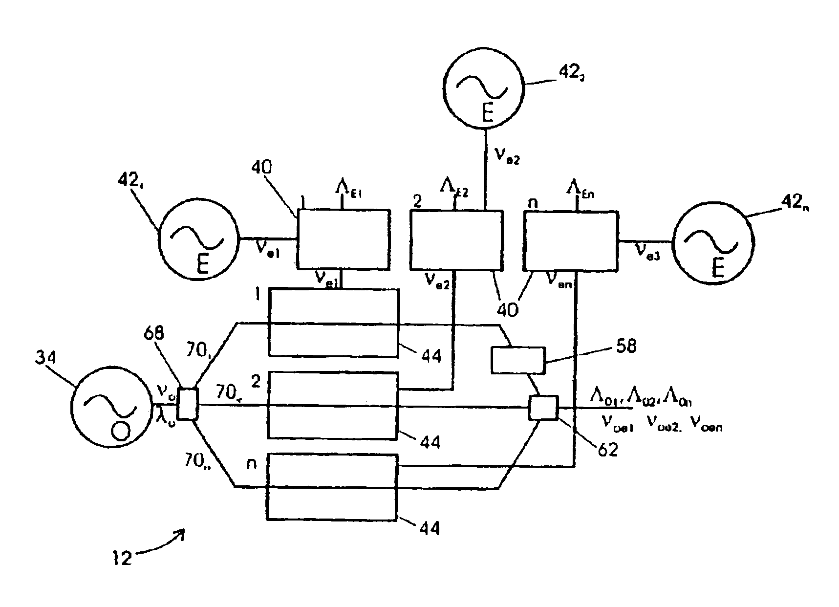
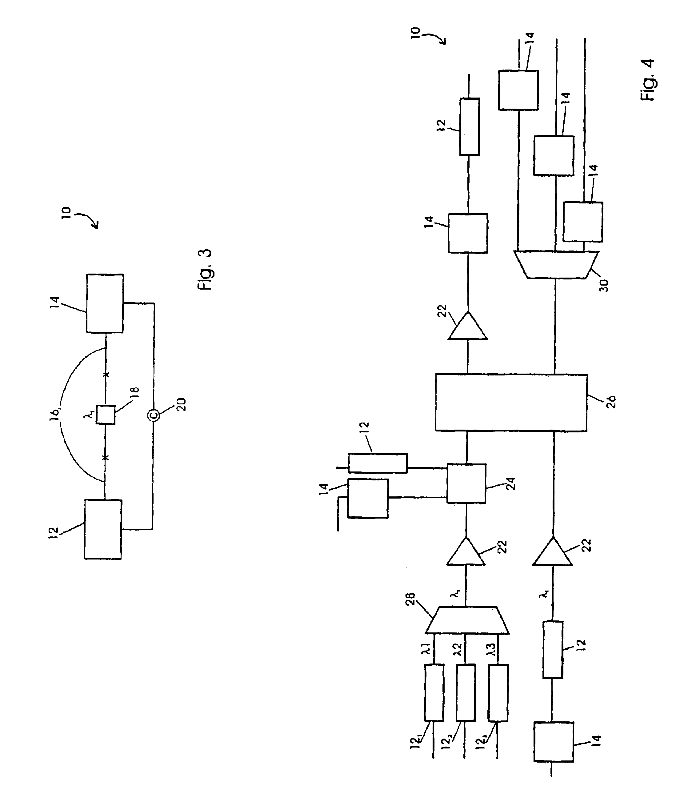
[0038]The operation of optical systems 10 of the present invention will be described generally with reference to the drawings for the purpose of illustrating present embodiments only and not for purposes of limiting the same. As shown in FIG. 3, the system 10 includes an optical transmitter 12 configured to transmit information, i.e., data, etc., via one or more information carrying optical wavelengths λi to an optical receiver 14 through one or more segments of optical fiber 16j. The system 10 may also include one or more dispersion compensating components18 and feedback controllers 20, as well as other optical components such as optical amplifier 22, add / drop devices 24, and the like.

[0039]As shown in FIG. 4, the system 10 can be embodied as a network including a plurality of transmitters 12 and receivers 14 in optical communication through one or more optical switches 26, combiners 28, and / or distributors 30. For example, optical and digital cross connect switches and routers, mu...


PUM

PropertyMeasurementUnit
wavelength rangeaaaaaaaaaa
angleaaaaaaaaaa
carrier frequencyaaaaaaaaaa

Abstract

Apparatuses, methods, and systems are disclosed for controlling optical signal wavelength spacing by providing for simultaneous upconversion of a plurality of electrical signal on subcarrier frequencies of an optical carrier frequency with or without modulation of an electrical data signal onto the optical carrier frequency. The optical carrier lightwave is split into a plurality of split lightwaves upon which one or more electrical frequencies carrying information can be upconverted onto optical subcarriers of the lightwave carrier frequency. The relative spacings of the optical subcarrier lightwaves will thus be unaffected by variation in the carrier frequency. The optical subcarrier lightwaves can then be recombined to form the optical data signal carrying the plurality of information carried by the electrical frequencies.

Description

CROSS-REFERENCE TO RELATED APPLICATIONS[0001]This application is a continuation of U.S. patent application Ser. No. 10 / 178,404, filed Jun. 24, 2002, now U.S. Pat. No. 6,633,690 which is a continuation application of U.S. patent application Ser. No. 09 / 663,763, filed Sep. 18, 2000, now U.S. Pat. No. 6,456,750, which is a continuation application of U.S. patent application Ser. No. 09 / 185,816, filed Nov. 4, 1998, now U.S. Pat. No. 6,292,598, which are incorporated herein by reference, and which is related to commonly assigned U.S. patent applications Ser. No. 09 / 185,821, entitled “Optical Distortion Compensation Apparatuses, Methods, and Systems”, and Ser. No. 09 / 185,820, now U.S. Pat. No. 6,118,566, entitled “Optical Upconverter Apparatuses, Methods, and Systems”, which are incorporated herein by reference.STATEMENT REGARDING FEDERALLY SPONSORED RESEARCH OR DEVELOPMENT[0002]Not ApplicableBACKGROUND OF THE INVENTION[0003]The present invention is directed generally to the transmission ...

Claims


Application Information

Patent Timeline
Patent Type & Authority Patents(United States)
IPC IPC(8): G02F1/01G02F1/225H04J14/02H04B10/18
CPCG02F1/225H04J14/0298H04B10/2507H04J14/02
Inventor PRICE, ALISTAIR J.ANTONE, MICHAEL C.
Owner OPTIC153 LLC
Why Eureka
Try Eureka