Fiber optical illumination system

Inactive Publication Date: 2005-05-10
NEGEVTECH
View PDF85 Cites 32 Cited by
  • Summary
  • Abstract
  • Description
  • Claims
  • Application Information

AI Technical Summary

Benefits of technology

[0023]In accordance with still a further preferred embodiment of the present invention, there is also provided a method of reducing the transmission loss in a fiber optical bundle for reducing the coherence of light transmitted therethrough, at least part of which light has a characteristic coherence length, the method comprising the steps of providing at l

Problems solved by technology

The nature of a laser beam, and especially its coherent nature, presents a number of problems when used as an illuminating source in applications requiring a uniform illuminating flux over the inspected area, such as is required, for instance, in a wafer inspection system:(i) Interference of light in the illumination optics creates non-uniformity in

Method used


Image

  • Fiber optical illumination system
  • Fiber optical illumination system
  • Fiber optical illumination system

Examples


Embodiment Construction

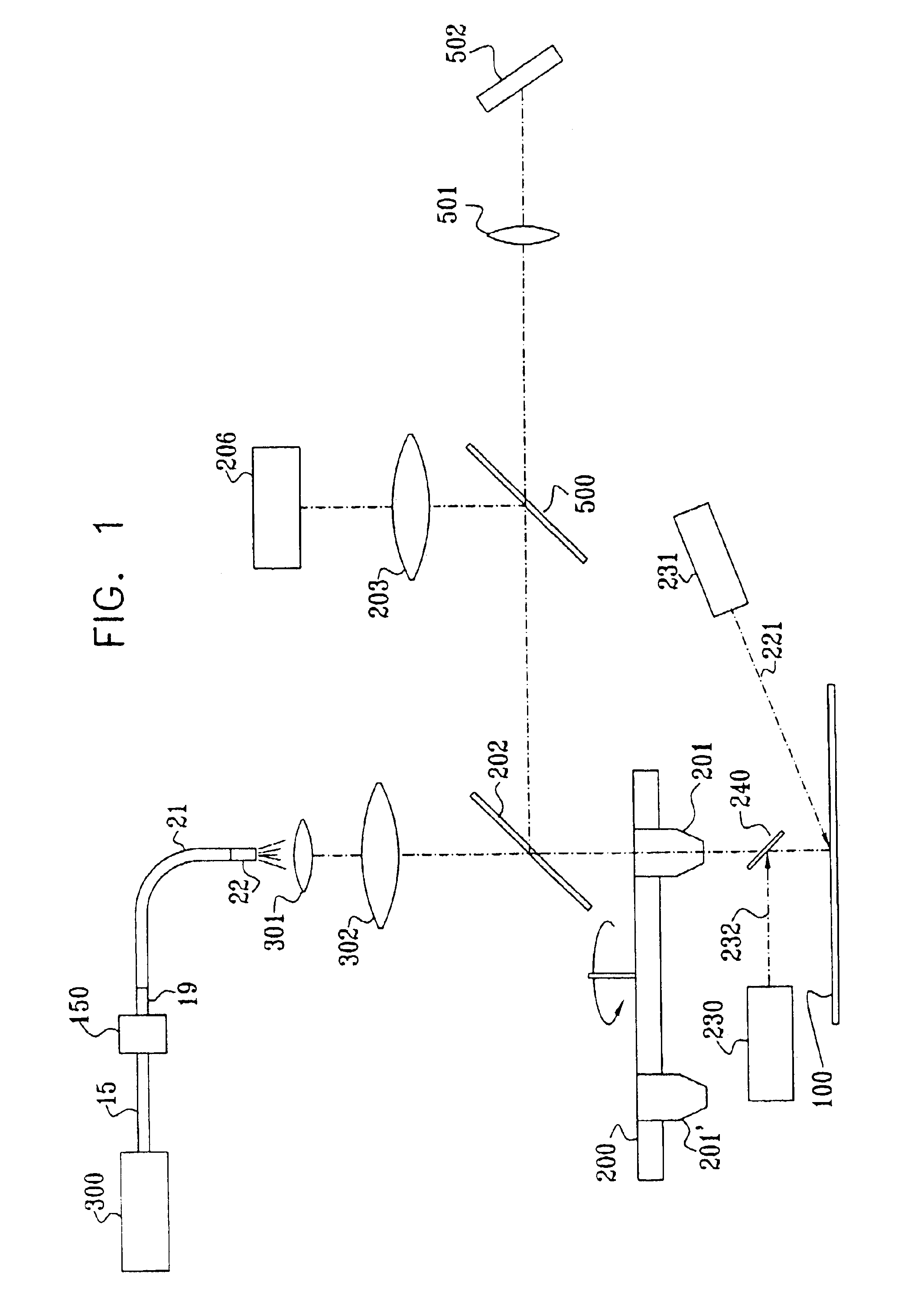
[0032]Reference is now made to FIG. 1, which is an overall schematic side view of the complete illumination system of the defect detection apparatus, according to one preferred embodiment of the present invention. According to different preferred methods of operation, three alternative modes of illumination are provided: Bright Field (BF), Side-illuminated Dark Field (DF) and Orthogonal or Obscured Reflectance Dark Field (ODF). Each mode of illumination is used to detect different types of defects in different production process steps. For example in order to detect an embedded defect in a transparent layer, such as silicon oxide, BF illumination is preferred. In order to detect a small particle on a surface, DF illumination generally yields better results.

[0033]In bright field illumination in general, the illumination is incident on the sample through the same objective lens as is used for viewing the sample. Reference is now made to FIG. 1, which shows a bright field illuminating ...


PUM


Abstract

A fiber optical illumination delivery system, which is effective in reducing the effects of source coherence. The system preferably utilizes either a single bundle of optical fibers, or serial bundles of optical fibers. In the single bundle embodiment, the differences in optical lengths between different fibers of the bundle is preferably made to be equal to even less than the coherence length of the source illumination. In the serial bundle embodiment, the fibers in the other bundle are arranged as groups of fibers of the same length, and it is the difference in lengths of these groups which is made equal to, or even more preferably, less than the overall difference in length between the shortest and the longest fibers in the other bundle. Both of these fiber systems enable construction of illumination systems delivering a higher level of illumination, but without greatly affecting the coherence breaking abilities of the system, thus enabling a generally more applicable system to be constructed.

Description

FIELD OF THE INVENTION[0001]The present invention relates to the field of fiber optical systems for illumination of objects to be imaged, and especially to ways of reducing speckle effects arising from the coherence of the illumination source used.BACKGROUND OF THE INVENTION[0002]The nature of a laser beam, and especially its coherent nature, presents a number of problems when used as an illuminating source in applications requiring a uniform illuminating flux over the inspected area, such as is required, for instance, in a wafer inspection system:[0003](i) Interference of light in the illumination optics creates non-uniformity in the illumination field.[0004](ii) Interference of the illuminated light by the structured pattern on the wafer creates artifacts in the image.[0005](iii) Surface roughness creates speckle, that generates non-uniformity in the image.[0006](iv) The laser beam itself is generally not uniform. Using the laser beam directly as a light source creates non-uniform...

Claims


Application Information

Patent Timeline
IPC IPC(8): G02B27/48G02B6/04G02B6/42G01N21/95
CPCG02B27/48G02B6/4298G02B6/04G01N21/9501G01N2021/479G02B6/4206G02B6/00
Inventor FURMAN, DOVNEUMANN, GADDOTAN, NOAM
Owner NEGEVTECH
Why Eureka
Try Eureka