Method and apparatus for measuring and controlling solids composition of a magnetorheological fluid

a technology of magnetorheological fluid and solids composition, which is applied in the direction of valve operating means/release devices, manufacturing tools, lapping machines, etc., can solve the problems of mr fluid being relatively unstable, prone to errors, and prone to problems

Inactive Publication Date: 2005-05-17
QED TECH INT
View PDF5 Cites 9 Cited by
  • Summary
  • Abstract
  • Description
  • Claims
  • Application Information

AI Technical Summary

Benefits of technology

[0019]FIG. 2 is a simplified schematic diagram of an MR finishing machine including an MR fluid dispensing and concentration control system in accordance with the invention;
[0020]FIG. 3 is a schematic d...

Problems solved by technology

MR fluid is a relatively unstable suspension because the magnetic particles tend readily to agglomerate and to settle out of suspension and thereby stagnate.
Although this method can yield excellent results, several problems can be encountered.
Pressure and flow rate must both be measured, and each may be subject to error.
A relatively long (100×diameter) capillary tube is required to provide the needed accuracy, and changes in capillary tube internal geometry (clogging, sedimentation, wear) can lead to erroneous values.
Again, several problems can be enco...

Method used


Image

  • Method and apparatus for measuring and controlling solids composition of a magnetorheological fluid
  • Method and apparatus for measuring and controlling solids composition of a magnetorheological fluid
  • Method and apparatus for measuring and controlling solids composition of a magnetorheological fluid

Examples


Embodiment Construction

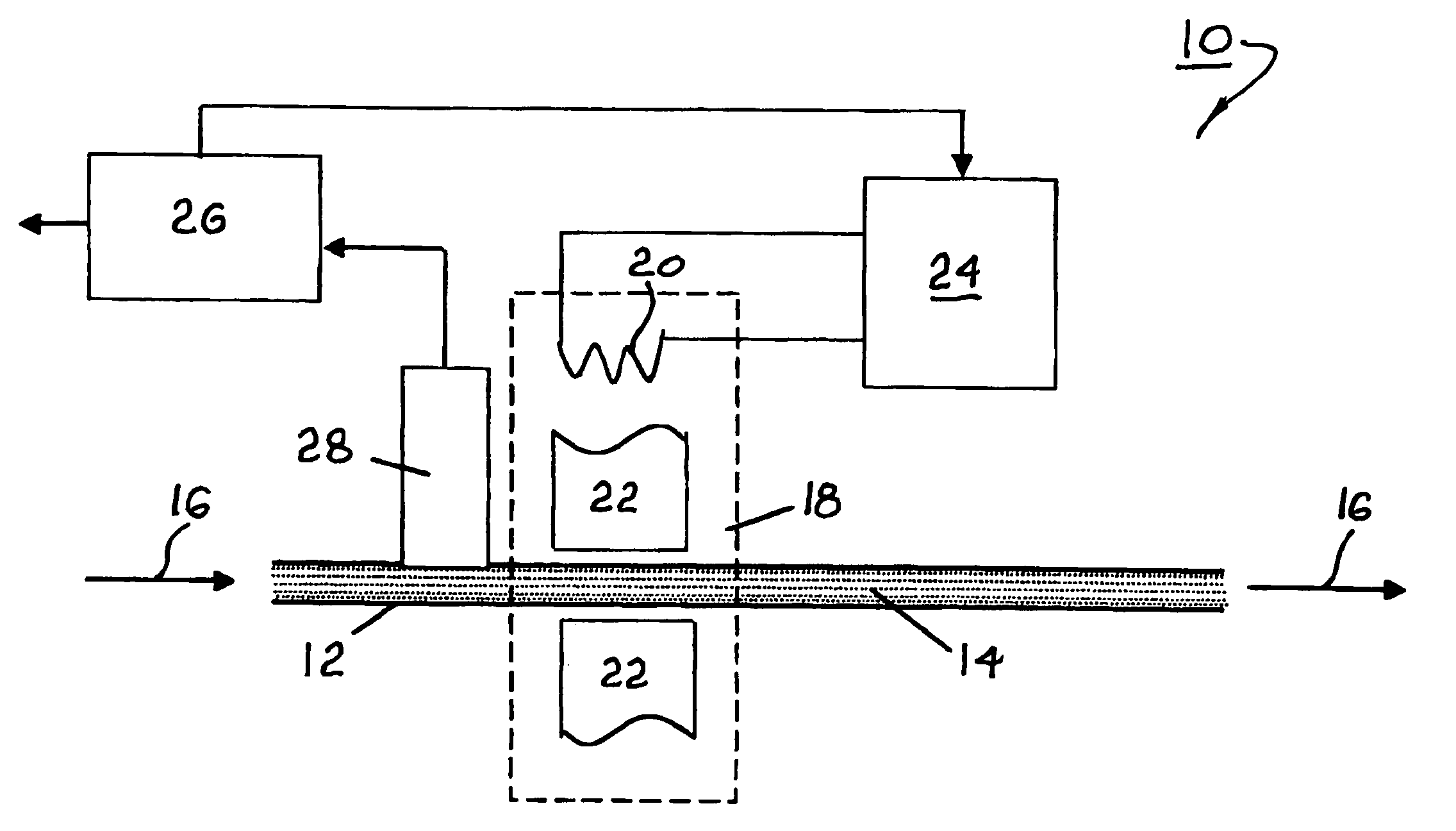
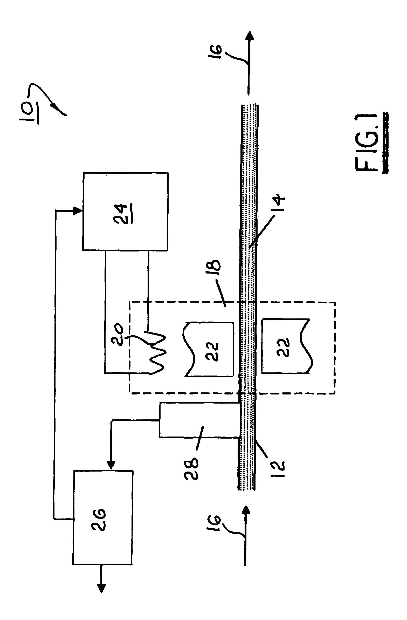
[0022]Referring to FIG. 1, a system 10 for measuring and adjusting by dilution the concentration of iron particles in a magnetorheological fluid includes a non-magnetic tube 12 for conveying a stream 14 of MR fluid 16 comprising a slurry of iron particles in a liquid. Stream 14 originates in a reservoir and pump, not shown in FIG. 1. An electromagnet 18 defines a magnetic flow control valve for variably stiffening a magnetorheological fluid passing therethrough to increase viscous drag of the fluid in the valve. Electromagnet 18 may comprise first and second pole pieces 22 disposed on opposite sides of tube 12. In a currently preferred embodiment, valve 18 comprises first and second magnet pole pieces 22 coaxially disposed and each having an axial passage therethrough, and electrical windings 20 connected to a power supply 24 for controllably providing a magnetic field within tube 12 disposed within the pole piece axial passages in response to energizing signals from computer 26. A...


PUM

PropertyMeasurementUnit
Pressureaaaaaaaaaa
Compositionaaaaaaaaaa
Flow rateaaaaaaaaaa

Abstract

A system for dispensing magnetorheological fluid to an MR finishing machine includes a pump for pressurizing the system; a first magnetic valve for regulating MR fluid flow by magnetically varying the structure and apparent viscosity of the fluid through a first flow passage; a similar second magnetic valve magnetically controlling a second flow passage in line with the first valve and flow passage; a pressure sensor disposed between the first and second valves; and an electronic control means. MR fluid flow through the system is controlled to a predetermined flow rate solely by the first valve. When the second valve is deactivated, a reference pressure is determined and saved. When the second valve is activated, a second pressure is determined and saved. From the pressure difference, the solids concentration of the fluid is determined, and a computer algorithm adds a calculated amount of water to the fluid reservoir as needed. The second valve is deactivated, and the measurement cycle is repeated, as may be desired.

Description

RELATIONSHIP TO OTHER APPLICATIONS AND PATENTS[0001]The present application is a Continuation-In-Part of a pending U.S. patent application Ser. No. 09 / 862,245, filed May 22, 2001.BACKGROUND OF THE INVENTION[0002]1. Field of the Invention[0003]The present invention relates to methods and apparatus for measuring the solids concentration of a fluid suspension; and more particularly, to methods and apparatus for monitoring and controlling the concentration of magnetic particles in a magnetorheological fluid being used in a magnetorheological finishing apparatus.[0004]2. Discussion of the Related Art[0005]It is well known in the art of finishing and polishing surfaces to use, as a finishing agent, particulate fluid suspensions having magnetorheological properties. Such fluids, known as magnetorheological fluids (MR fluids), comprise magnetically soft particles, such as iron carbonyl, which can become oriented and magnetically linked into fibrils in the presence of a superimposed magnetic...

Claims


Application Information

Patent Timeline
IPC IPC(8): B24B31/00B24B31/112B24B57/04B24B57/00F16K31/06F16K13/00F16K13/10B24B57/02B24B1/00B24B37/00B24B49/00
CPCB24B1/005B24B31/112F16K13/10F16K31/06B24B57/04Y10S137/909Y02P70/10
Inventor KORDONSKI, WILLIAMNATKIN, MICHAELGORODKIN, SERGEI
Owner QED TECH INT
Why Eureka
Try Eureka