
Angiopathy diagnosing apparatus

a technology of angiopathy and diagnostic equipment, which is applied in the field of angiopathy diagnostic equipment, can solve the problems of difficult to obtain, insufficient related information, and difficulty in obtaining from the subject, and achieve the effects of high accuracy, quick diagnosis and high accuracy

Inactive Publication Date: 2005-05-17
OMRON HEALTHCARE CO LTD
View PDF12 Cites 18 Cited by
  • Summary
  • Abstract
  • Description
  • Claims
  • Application Information

AI Technical Summary

Benefits of technology

[0009]It is therefore an object of the present invention to provide an angiopathy diagnosing apparatus which can diagnose angiopathy, with high accuracy, based on pulse-wave-propagation-velocity-related information.
[0012]According to this invention, the first pulse-wave-propagation-velocity-related-information obtaining device and the second pulse-wave-propagation-velocity-related-information obtaining device obtains, at a substantially same time, a first pulse-wave-propagation-velocity-related information at the first interval, and a second pulse-wave-propagation-velocity-related information at the second interval, respectively, and the comparison-value calculating means calculates a comparison value based on the first pulse-wave-propagation-velocity-related information and the second pulse-wave-propagation-velocity-related information. Although pulse-wave-propagation-velocity-related information changes in relation with blood pressure as well as angiopathy, the comparison value is calculated based on the two pieces of pulse-wave-propagation-velocity-related information obtained at the substantially same time, and accordingly the comparison value is free of the influence of change of the blood pressure. Thus, angiopathy can be diagnosed, with high accuracy, based on the comparison value. In addition, since pulse-wave propagation velocity can be measured between two arbitrary locations of the subject, angiopathy can be diagnosed on an arbitrary body portion of the subject other than an inferior limb of the subject. Moreover, since pulse-wave-propagation-velocity-related information can be easily obtained from even an inferior limb of the subject, angiopathy of the inferior limb can be diagnosed with high accuracy. Furthermore, since a piece of pulse-wave-propagation-velocity-related information can be obtained in synchronism with each heartbeat of the subject, a quick diagnosis can be made.

Problems solved by technology

However, it is difficult to obtain, from the subject, every piece of pulse-wave-propagation-velocity-related information when the subject has the standard blood pressure.
However, since the accuracy of the diagnosis based on the pulse-wave-propagation-velocity-related information is not sufficiently high, a patient who, in fact, is free of angiopathy may be suspected of the disease based on the information, i.e., may be erroneously judged as needing a diagnosis using a CT device.
On the other hand, each CT device is very expensive and accordingly a sufficient number of CT devices cannot be purchased.
However, the upper-and-lower-limb blood-pressure measuring device cannot diagnose arteriostenosis on the other body portions than the inferior limbs.
In addition, this device cannot sufficiently accurately measure the inferior-limb blood-pressure values, and accordingly the reliability of the index values determined by the device is not sufficiently high.
Moreover, this device needs a considerably long time to measure the blood-pressure values.

Method used


Image

  • Angiopathy diagnosing apparatus
  • Angiopathy diagnosing apparatus
  • Angiopathy diagnosing apparatus

Examples


Embodiment Construction

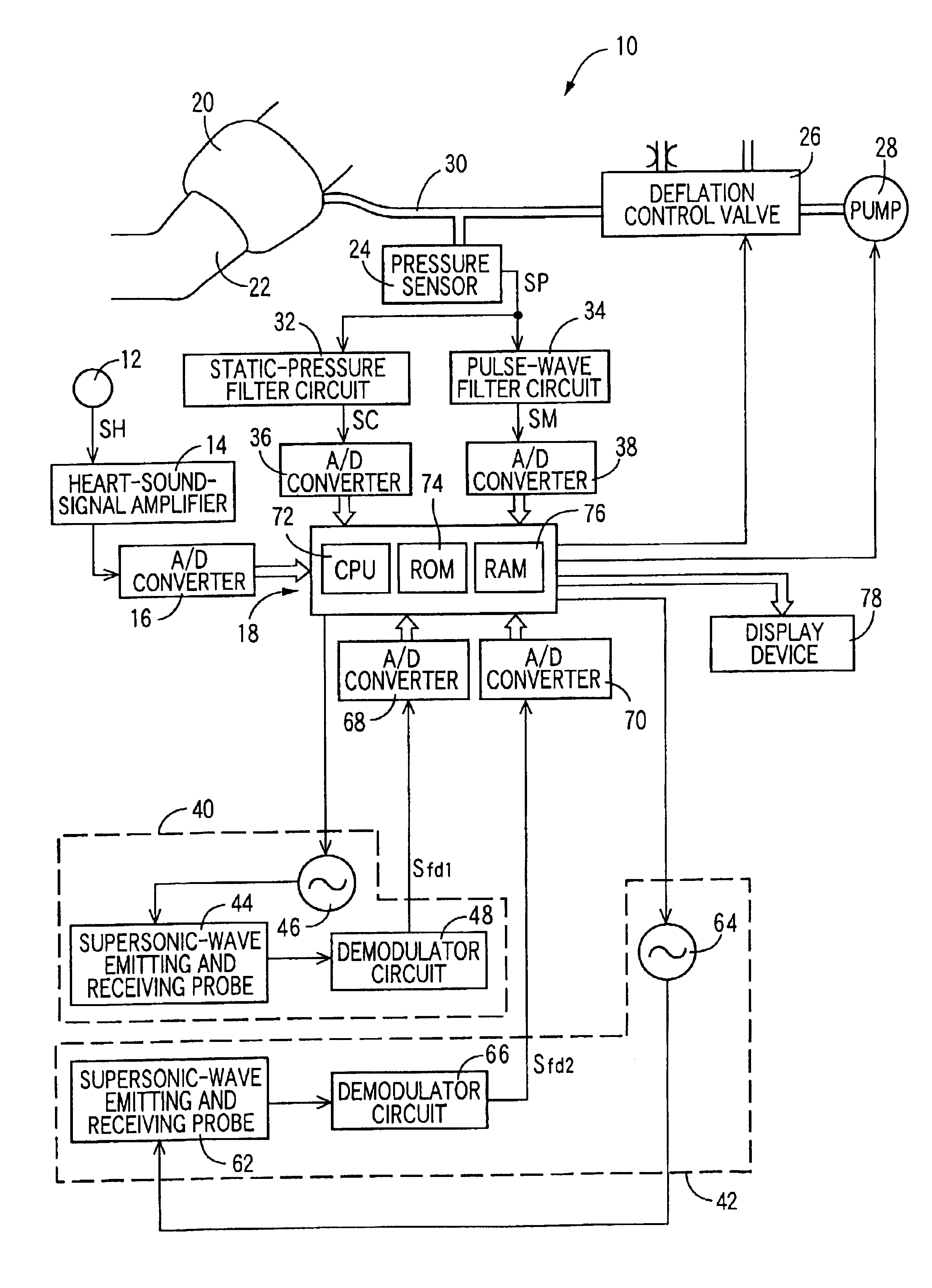
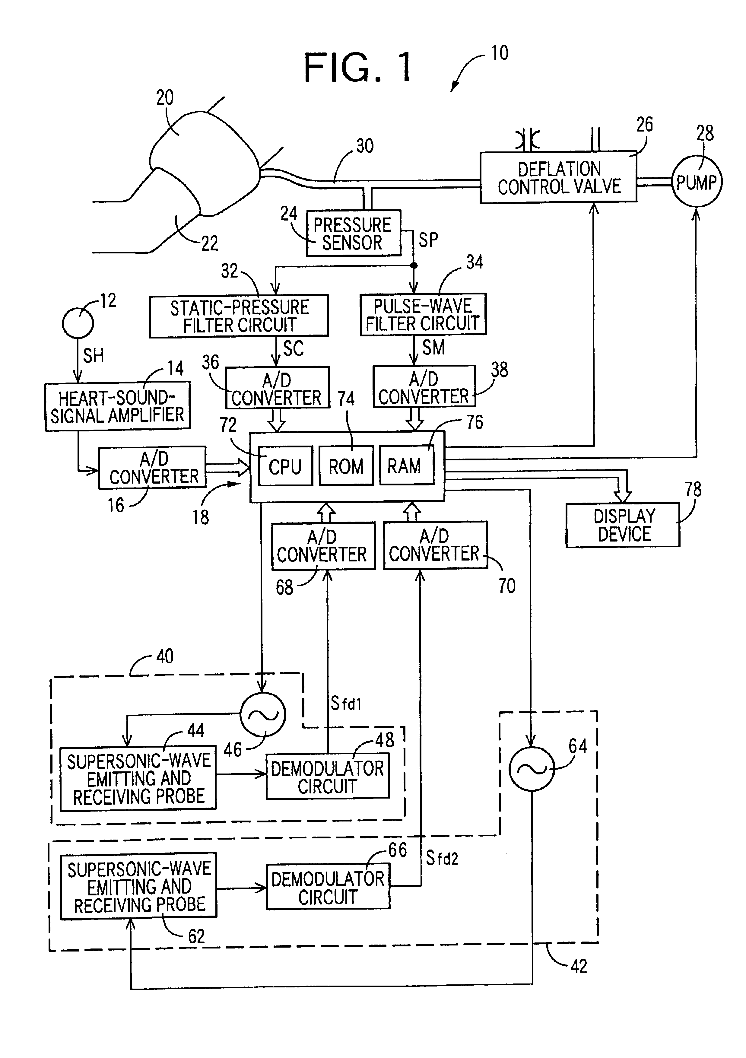
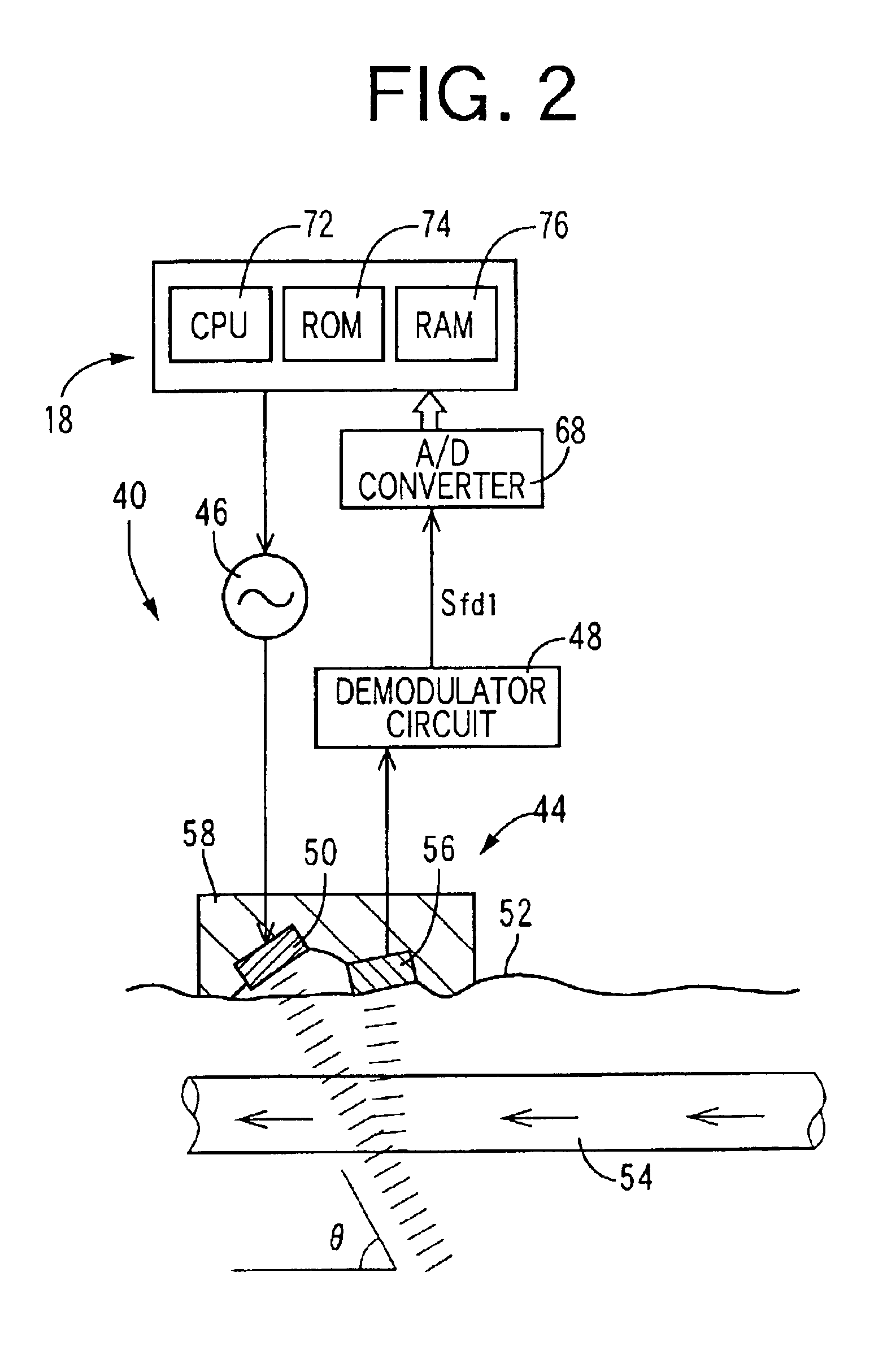
[0019]Hereinafter, there will be described in detail a preferred embodiment of the present invention, by reference to the drawings. FIG. 1 is a view showing a construction of an angiopathy diagnosing apparatus 10 to which the present invention is applied.

[0020]The present apparatus includes a heart-sound microphone 12 functioning as a first heartbeat-synchronous-signal detecting device. The microphone 12 is attached, with an adhesive tape, not shown, to a chest of a living subject, not shown. The microphone 12 is for detecting heart sounds as a heartbeat-synchronous signal produced from an upstream-side-end of a prescribed first interval of the subject. The microphone 12 incorporates a piezoelectric element, not shown, which converts the heart sounds produced from the heart of the subject, into an electric signal, i.e., a heart-sound signal SH. A heart-sound-signal amplifier 14 includes four different filters, not shown, that attenuate, for clearly recording a high-pitched sound com...


PUM


Abstract

An apparatus for diagnosing an angiopathy of a living subject, including a first pulse-wave-propagation-velocity-related-information obtaining device which obtains a first pulse-wave-propagation-velocity-related information that is related to a first velocity at which a first pulse wave propagates through a first interval of the subject, a second pulse-wave-propagation-velocity-related-information obtaining device which obtains, at a substantially same time as a time when the first pulse-wave-propagation-velocity-related-information obtaining device obtains the first pulse-wave-propagation-velocity-related information, a second pulse-wave-propagation-velocity-related information that is related to a second velocity at which a second pulse wave propagates through a second interval of the subject that is different from the first interval, and a comparison-value calculating device for calculating a comparison value based on the first pulse-wave-propagation-velocity-related information and the second pulse-wave-propagation-velocity-related information.

Description

BACKGROUND OF THE INVENTION[0001]1. Field of the Invention[0002]The present invention relates to an angiopathy diagnosing apparatus for diagnosing an angiopathy of a living subject, such as arteriosclerosis or arteriostenosis.[0003]2. Related Art Statement[0004]It is practiced to obtain, for diagnosing an angiopathy such as arteriosclerosis, arteriostenosis, aneurysm, or dissecting aneurysm, pulse-wave-propagation-velocity-related information that is related to a velocity at which a pulse wave propagates through an artery between two prescribed portions of a living subject; such as pulse-wave propagation velocity itself or pulse-wave propagation time. Since, for example, pulse-wave propagation velocity increases as arteriosclerosis advances, and conversely decreases as arteriostenosis advances, it is possible to diagnose those sorts of angiopathy based on the pulse-wave propagation velocity.[0005]The pulse-wave-propagation-velocity-related information is also obtained for evaluating...

Claims


Application Information

Patent Timeline
Patent Type & Authority Patents(United States)
IPC IPC(8): A61B5/026A61B5/0285A61B7/00A61B7/04A61B8/06A61B8/08A61B5/0205A61B5/0245A61B5/02
CPCA61B5/02007A61B5/02125A61B5/0285A61B8/06A61B7/04A61B8/488A61B8/08
Inventor KAWAGUCHI, OSAMUNARIMATSU, KIYOYUKI
Owner OMRON HEALTHCARE CO LTD
Learn More