Powder feed splitter for hand-held laser powder fusion welding torch

a laser powder fusion and splitter technology, which is applied in the field of splitters, can solve the problems of less developed powder flow splitter art, powder to stick and resist the forward travel of powder, and achieve the effect of reliable and/or adjustable, reducing clogging

Inactive Publication Date: 2005-05-17
HONEYWELL INT INC
View PDF34 Cites 7 Cited by
  • Summary
  • Abstract
  • Description
  • Claims
  • Application Information

AI Technical Summary

Benefits of technology

[0013]The present invention provides a powder flow splitter that is reliable and / or adjustable. In particular, the inventive splitter reduces clogging and / or allows output flow adjustability and / or can provide fluid powder flow despite gravitational forces. In particular, and by way of example only, the splitter may include a distribution assembly with smooth interior surfaces that generally prevent the powder from sticking or clogging. The splitter also may enable adjustable powder flow distribution between the outgoing lines as well as selectably control the pressure downstream from the powder flow splitter.
[0018]Smooth surfaces inside the powder feed splitter and mediating surfaces between transition surfaces enable the powder to flow smoothly with lower risk of blockages or clogging.

Problems solved by technology

Otherwise, separate, independent, and generally-expensive feed powder reservoirs and systems would be used where multiple feed powder lines are needed.
While the art of providing nozzles for laser welding torches is well developed, the art of powder flow splitters is less developed.
Some of the problems arising with the splitting of fusion powder flow relate to aberrations or flaws within the flow lines or system design, which can cause the powder to stick and resist the forward travel of the powder.
Additional problems may arise from the generation of static electricity from interparticle friction as well as the loss of downstream pressure during the powder flow splitting process.
Additionally, in one known splitter design, there is no adjustability of the output flow streams to vary powder and fluid flow between the various output flow streams.
Under certain circumstances, this powder feed splitter is subject to clogging which dramatically interferes with the operation of any process relying upon the split powder feed.
This may involve dismantling the splitter and interrupting the laser fusion process that is dependent upon the split powder flow.
Additionally, no gas pressure is used in the conventional splitter configuration, above, to enhance powder flow.
Additionally, because the powder feed output lines do not travel outwardly straight from the powder feed splitter, but instead radiate outward at an angle, additional clogging may occur in the powder flow lines.
Due to both the loose fit between the powder feed splitter halves and the inability to reliably and selectively control the incoming powder flow within the powder splitting portion, it is difficult to repeatably align and adjust such a previously-known powder feed splitter.

Method used


Image

  • Powder feed splitter for hand-held laser powder fusion welding torch
  • Powder feed splitter for hand-held laser powder fusion welding torch
  • Powder feed splitter for hand-held laser powder fusion welding torch

Examples


Embodiment Construction

)

[0042]The detailed description set forth below in connection with the appended drawings is intended as a description of presently-preferred embodiments of the invention and is not intended to represent the only forms in which the present invention may be constructed and / or utilized. The description sets forth the functions and the sequence of steps for constructing and operating the invention in connection with the illustrated embodiments. However, it is to be understood that the same or equivalent functions and sequences may be accomplished by different embodiments that are also intended to be encompassed within the spirit and scope of the invention.

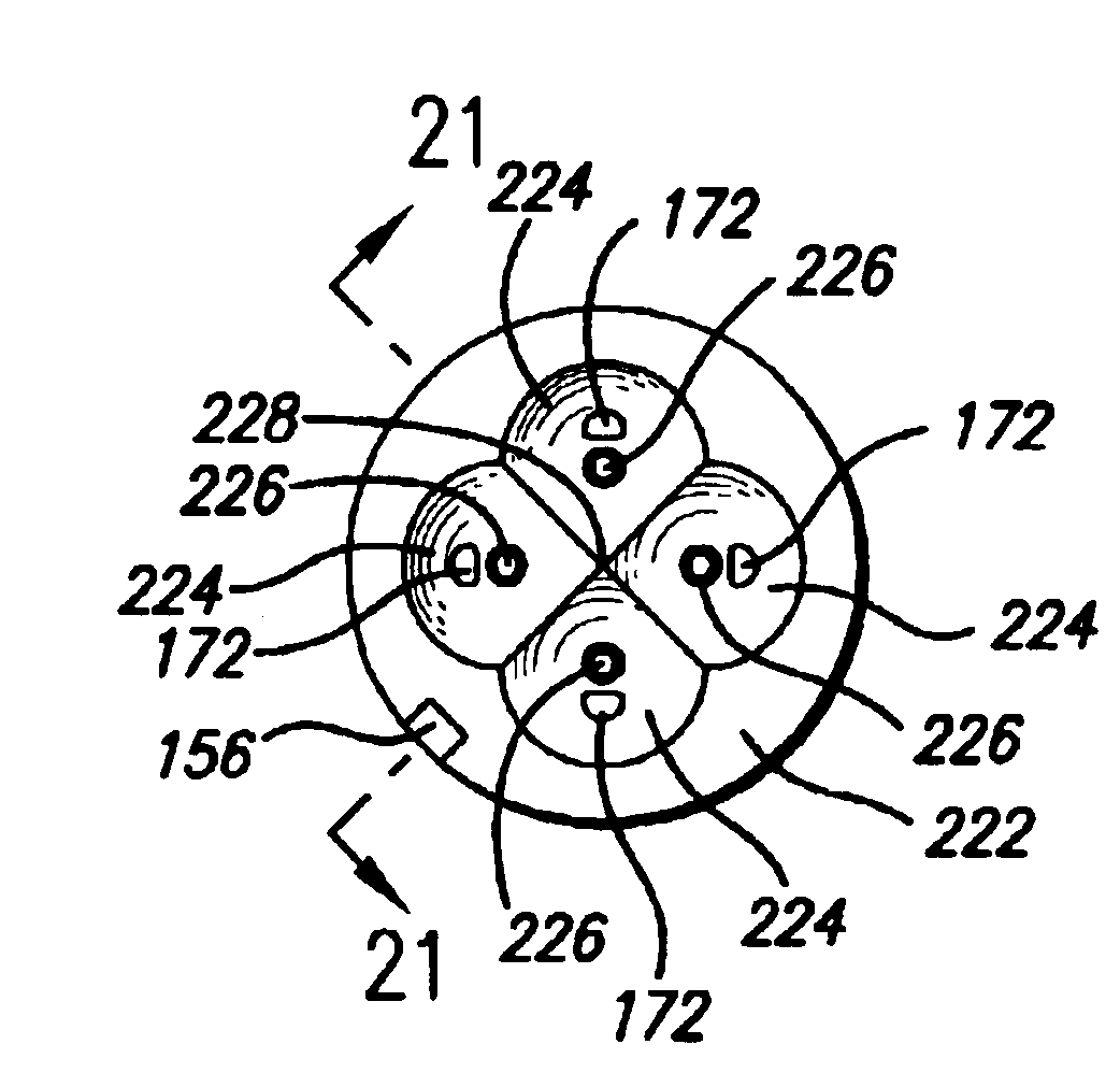
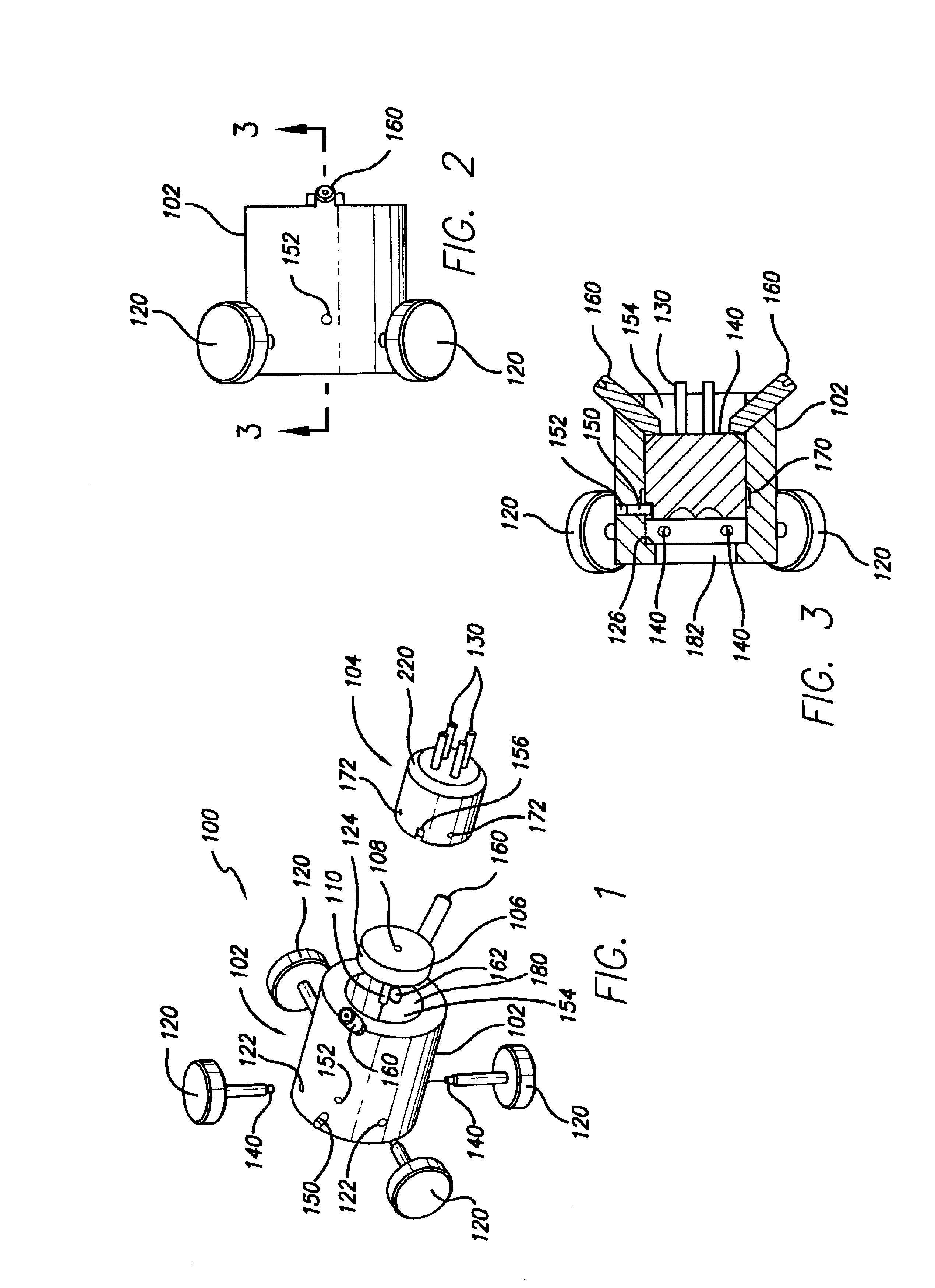
[0043]As shown in FIG. 1, the invention is embodied in a powder feed splitter 100 for hand-held or floor-mounted laser powder fusion welding torch systems or the like. The splitter is used to divide the flow of powder from a single incoming line to two or more, or in this case four, exiting or outflow lines. In doing so, additional gas...


PUM

PropertyMeasurementUnit
shapeaaaaaaaaaa
energyaaaaaaaaaa
areaaaaaaaaaaa

Abstract

A powder feed splitter and a machine using a powder feed splitter, to divide a powder flow into two or more streams in a predictable, adjustable, and reliable manner for use in material processing such as welding. A housing encloses an inlet disk having an inlet regulator preferably a disk, having an inlet tube which may be adjustable radially or laterally with respect to the housing. An adjustment mechanism can selectively move the inlet regulator to adjust the powder flow amongst the several powder outlet ports. Funnel-shaped cavities within the housing may have optional gas inlets to enable the introduction of additional gas to the separated powder flow streams. A one-way fit may be present between the interior powder flow splitter and the exterior casing. Smooth interior surfaces through the device prevent turbulence and buildup of powder.

Description

CROSS-REFERENCES TO RELATED APPLICATIONS[0001]This application is related to U.S. patent application Ser. No. 10 / 071,025 filed Feb. 8, 2002 entitled HAND-HELD POWDER-FED LASER FUSION WELDING TORCH, which is incorporated herein by reference.BACKGROUND OF THE INVENTION[0002]1. Field of the Invention[0003]This invention relates to powder fusion welding and more particularly to a splitter for a fluid and powder flow stream that enables a single stream of such powder flow to become several streams.[0004]2. Description of the Related Art[0005]With the increased use of lasers to provide powder fusion welding, articles can be constructed having net shape or near-net shape. This provides significant advantages as compared to casting or other component-making processes.[0006]In a powder fusion process, fusion material is fed to the active focus point of the welding tool, usually a laser or other energy source. The powder may contain a variety of different substances including particulate meta...

Claims


Application Information

Patent Timeline
Patent Type & Authority Patents(United States)
IPC IPC(8): B05B7/14B23K26/14B05B7/22B05B7/16B23K26/42B22F3/105
CPCB05B7/1413B23K26/1411B05B7/228B23K26/144
Inventor RENTERIA, FEDERICOHEHMANN, WILLIAM F.
Owner HONEYWELL INT INC
Why Eureka
Try Eureka