Engine generator apparatus

a generator and engine technology, applied in the direction of electric generator control, electric generator control, dynamo-electric converter control, etc., can solve the problems of unstable output of oxygen sensor, increased range of variation in engine number of revolutions, and increased risk of oxygen sensor detection signal instability, so as to achieve the effect of quick start of the control of the air-fuel ratio

Inactive Publication Date: 2005-05-17
HONDA MOTOR CO LTD
View PDF13 Cites 23 Cited by
  • Summary
  • Abstract
  • Description
  • Claims
  • Application Information

AI Technical Summary

Benefits of technology

[0017]According to the fourth feature, the engine is started in response to a heat request, in other words, the engine is started to generate electric power in a state where the electric load is already connected to the generator. Therefore, in this case, the control of an air-fuel ratio can be quickly started.

Problems solved by technology

However, if the revolution speed of the engine is set almost at a constant speed in the engine generator apparatus, when an electric load is eliminated or extremely reduced, the range of variation in the number of revolutions of the engine increases, so the detection signal of the oxygen sensor is likely to become unstable.
In this example, when the engine generator apparatus is released from the power network because of power failure, the load is also isolated at the same time to bring the engine generator apparatus into a no-load operation to increase variation in the number of revolutions, which is likely to cause an unstable output of the oxygen sensor.

Method used


Image

  • Engine generator apparatus
  • Engine generator apparatus
  • Engine generator apparatus

Examples


Embodiment Construction

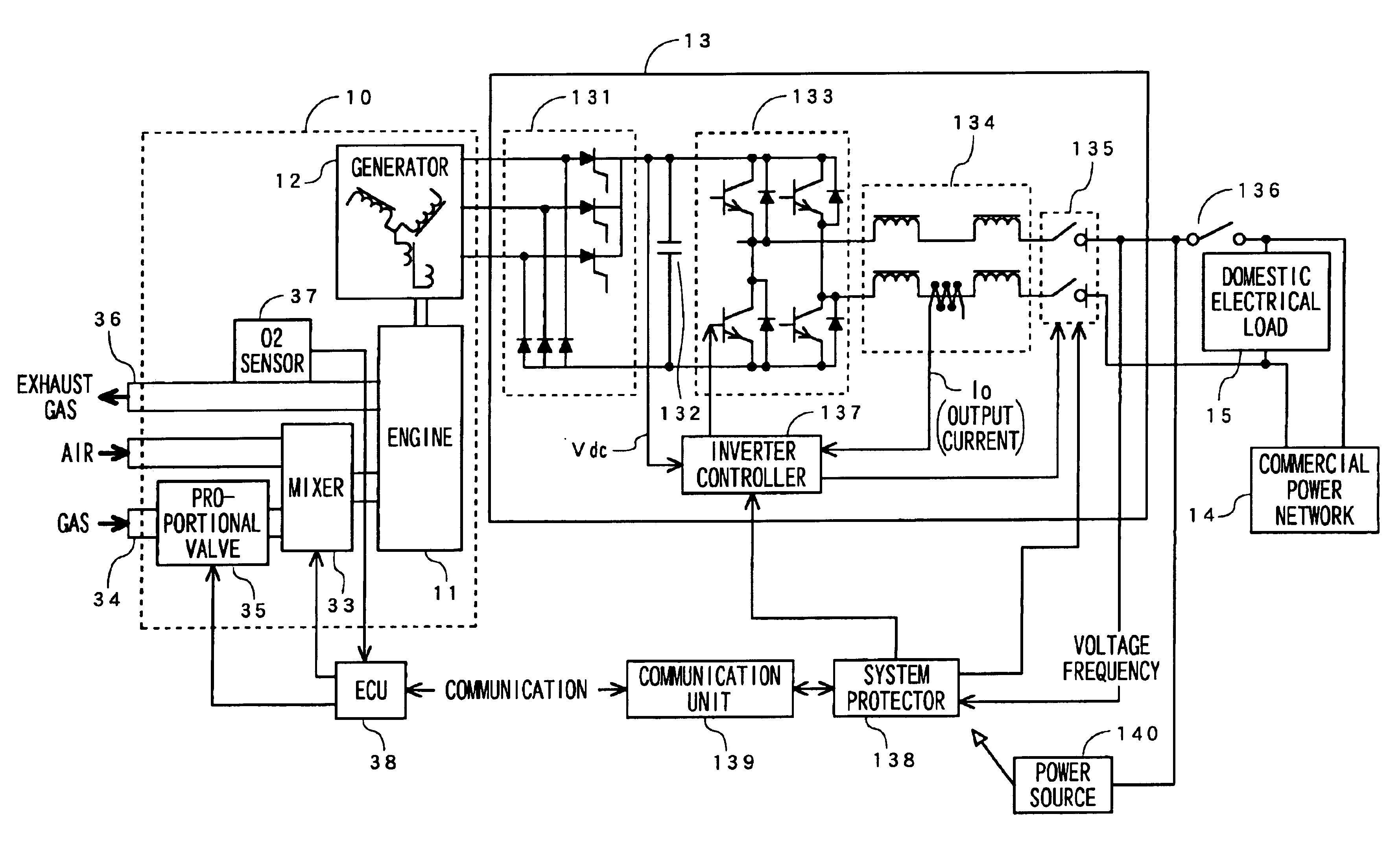
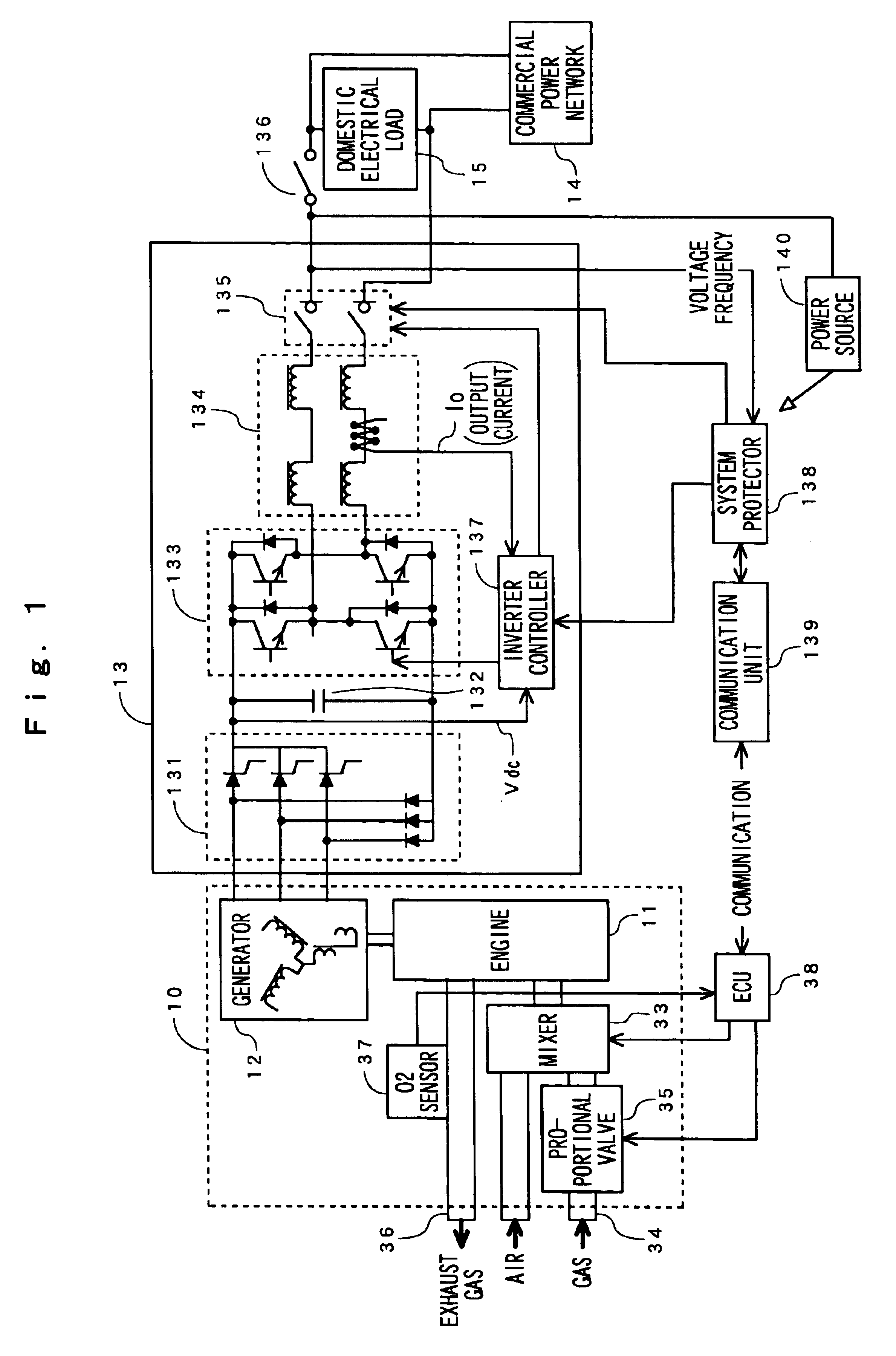
[0027]One embodiment of the present invention will be described in more detail referring to the relevant drawings. FIG. 1 is a block diagram of the engine generator apparatus. As shown, an engine generator 10 comprises an engine 11 and a generator 12. The generator 12 is driven by the engine 11 for generating an alternating current output responding to the number of revolutions. The generator 12 comprises a rotor joined to the engine 11 and a stator on which three phase windings are wound. The rotor and the stator are not shown in FIG. 1. The output terminal of the three phase windings is connected with an inverter unit 13. The inverter unit 13 converts the alternating current output of the generator 12 into an alternating current of the quality equivalent (in voltage, frequency, noise, and other factors) to that of the commercial power network, and then the output is interconnected with the commercial power network as timed in phase with the same of the network.

[0028]More specifica...


PUM


Abstract

An engine generator apparatus controls the air-fuel ratio in response to the stable output of an oxygen sensor. When a system protector 138 detects a disorder in a power network, it outputs failure signal. A connection relay 135 is opened in response to the failure signal to release connection of a generator to the power network to release load. When the failure signal is not detected, a load determination section 41 urges a proportional valve controller 40 and the controller 40 drives a valve 35 corresponding to the oxygen density to perform a control of the air-fuel ratio. The load determination section 41 determines that the load is released by the failure signal to send a notification of no load to the controller 40. The controller 40 stops the control of the air-fuel ratio based on the oxygen density in response to this notification.

Description

BACKGROUND OF THE INVENTION[0001]1. Field of the Invention[0002]The present invention relates to an engine generator apparatus and in particular, to an engine generator apparatus provided with a purifier of engine exhaust.[0003]2. Description of the Related Art[0004]In recent years, there has been a widespread use of compact generator apparatus capable of being easily installed relatively. Further, there are indications that a widespread use of co-generation type engine generator apparatus that not only generate electric power but also utilize exhaust heat generated when an engine for generating electric power is operated to enhance operation efficiency. A study of reducing the physical size of this type of engine generator apparatus for domestic use has been also conducted.[0005]In this kind of generator apparatus, in order to give special considerations to atmospheric environment, for example, in a case where a generator driven by a gasoline engine or a gas engine is used, the air...

Claims


Application Information

Patent Timeline
Patent Type & Authority Patents(United States)
IPC IPC(8): B60K6/04B60K6/00F02D41/14F01N11/00F02B63/04F02N11/08F02N11/04F02B63/00F02D41/08B60W10/06F02D29/06F02G5/04H02P9/04
CPCF01N11/007F02B63/04F02D41/1454F02N11/04F02N11/0803F02D29/06F02D41/083Y02T10/47F02D41/1488Y02E20/14Y02T10/166F02D41/1456Y02T10/12Y02T10/40
Inventor SHINOGI, YOSHIHISA
Owner HONDA MOTOR CO LTD
Why Eureka
Try Eureka