Thin brushless motor having ring-configured centralized power distribution unit

brushless motor technology, applied in the direction of coupling device connection, magnetic circuit rotating parts, magnetic circuit shape/form/construction, etc., can solve the problems of increasing the production cost of a centralized power distribution unit, most of the other parts of the metal plate other than the portions stamped out into a ring-like shape become wasted, etc., to achieve the effect of reducing the cost of molds, reducing material costs, and reducing material loss

Inactive Publication Date: 2005-05-17
SUMITOMO WIRING SYST LTD +1
View PDF44 Cites 31 Cited by
  • Summary
  • Abstract
  • Description
  • Claims
  • Application Information

AI Technical Summary

Benefits of technology

[0015]According to the invention, therefore, the material loss is remarkably reduced as compared with that in a conventional method. Therefore, the material cost of the bus bars can be reduced, and the cost of the mold can be lowered. As a result, the centralized power distribution unit can be produced at a low cost.
[0016]Preferably, when a linear bus bar body is stamped out by the press molding, the terminal portion and the tabs are integrally formed in a state where the terminal portion and the tabs are coupled to the bus bar body. In this case, a step of welding or the like is not necessary, and hence the production cost can be reduced as compared with the case where a terminal portion and tabs which are previously produced are later attached to the bus bar body. Therefore, the use of such bus bars enables the centralized power distribution unit to be produced at a low cost.
[0017]Preferably, the bus bars are stamped out in a

Problems solved by technology

Most of the portions of the metal plate other than the portions which are stamped out into the ring-like shape become wasted.
Therefore, conventionally, as seen from the above, t

Method used


Image

  • Thin brushless motor having ring-configured centralized power distribution unit
  • Thin brushless motor having ring-configured centralized power distribution unit
  • Thin brushless motor having ring-configured centralized power distribution unit

Examples


Embodiment Construction

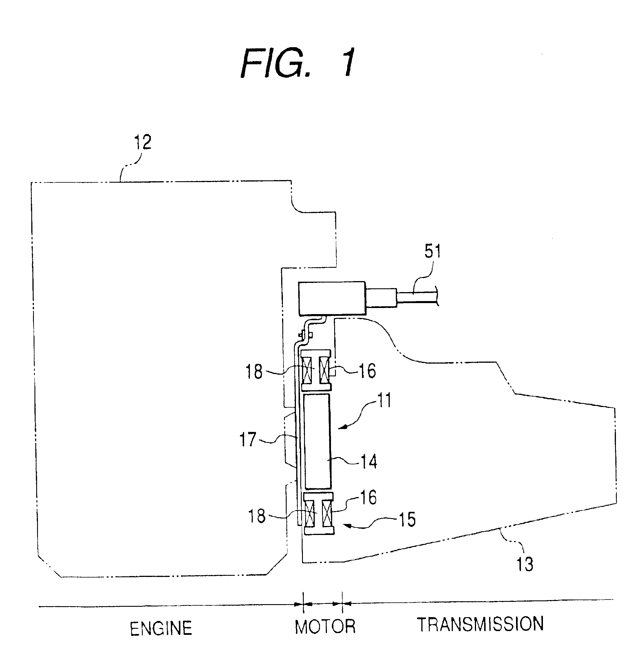
[0068]As shown in FIG. 1, a three-phase thin DC brushless motor 11 to be used in a hybrid automobile is disposed between an engine 12 and a transmission 13. The thin DC brushless motor 11 includes a rotor 14 connected, e.g., directly connected, to a crankshaft of the engine 12, and a ring-like stator 15 enclosing the rotor 14. The stator 15 includes a plurality of magnetic poles that have windings 16 on cores, a stator holder 18 that contains the magnetic poles, and an annular centralized distribution unit 17 that concentratedly distributes currents to the windings 16.

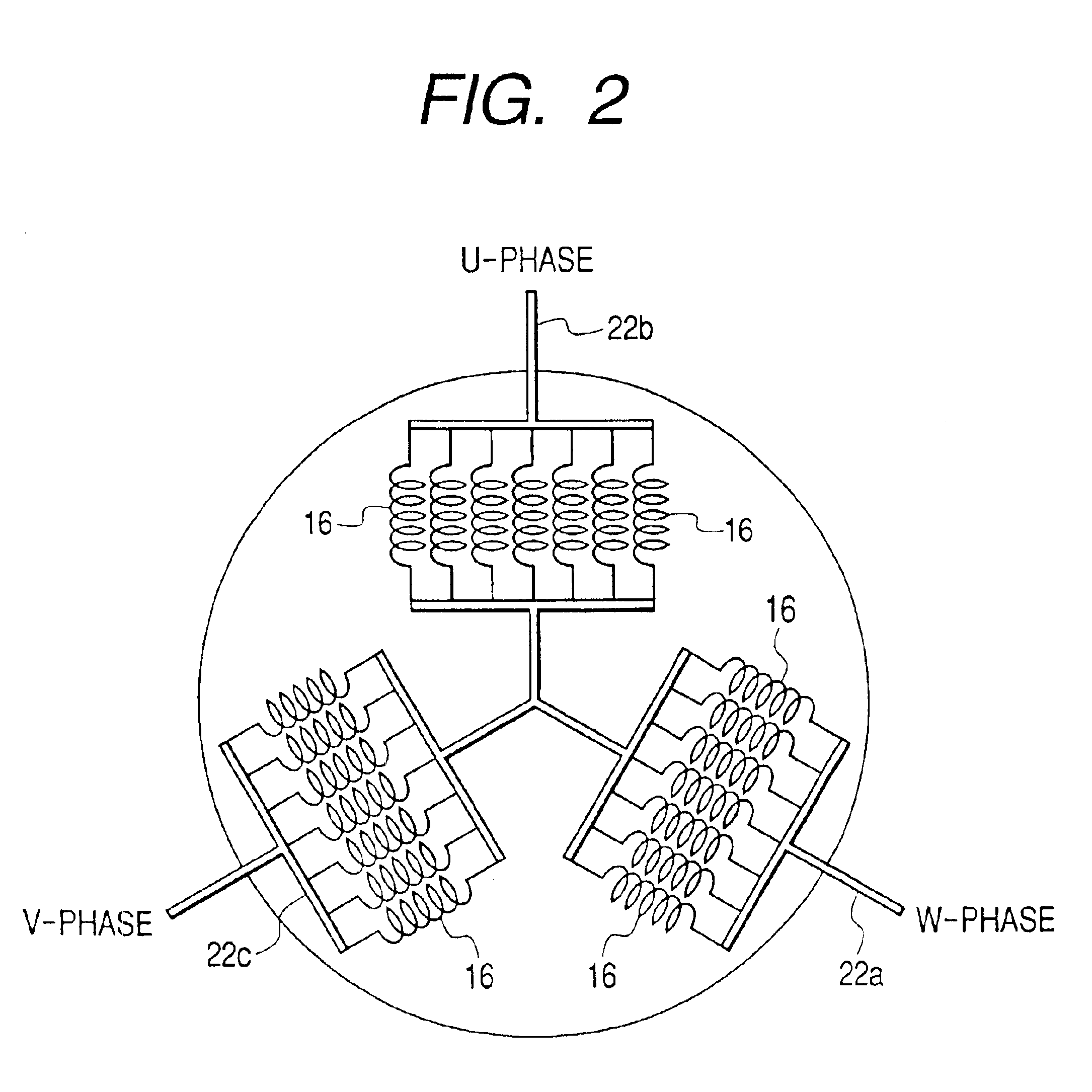
[0069]FIG. 2 shows a schematic diagram of the stator 15. As shown in FIG. 2, an end of each phase winding 16 is connected to one of bus bars 22a, 22b, and 22c formed in the centralized distribution unit 17 while the other end is connected to a ring-like conductive member (not shown).

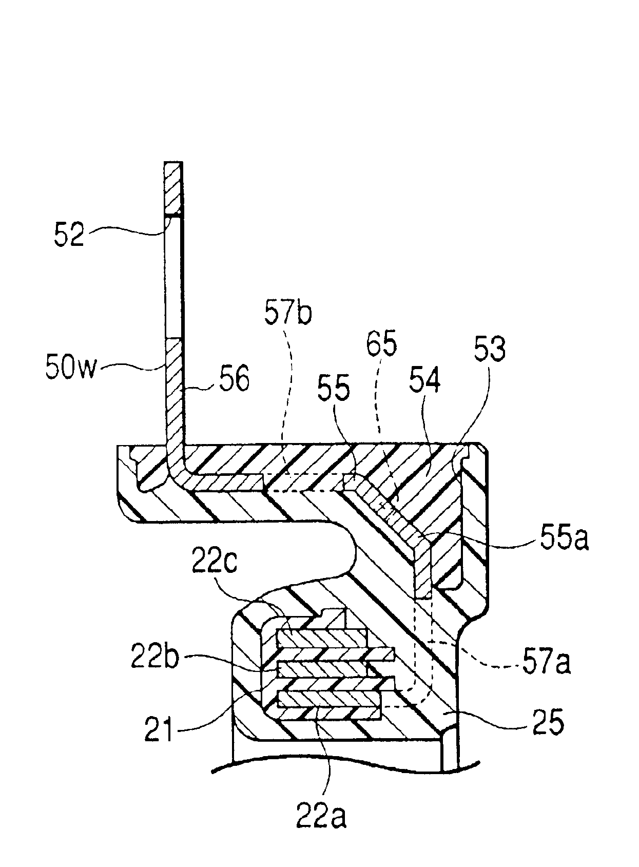
[0070]As shown in FIGS. 3 to 6, a continuous annular insulating holder 21 (FIGS. 6A and 6B) made of synthetic resin is embedded in the cen...


PUM


Abstract

A centralized power distribution unit for a vehicular thin brushless motor includes a plurality of bus bars and a resin insulating layer that covers the bus bars. The bus bars are disposed correspondingly with phases of the motor. Each of the bus bars has a terminal portion to be connected to a battery and one or more tabs to be connected respectively to one or more windings of a stator. Each of the bus bars is shaped into a substantially annular shape by bending a molded material in a thickness direction. The molded material is obtained by stamping out a conductive metal plate into a strip-like shape. Diameters of the annular shapes of the bus bars are set to be different from one another depending on the corresponding phase of the motor. The bus bars are stacked in a radial direction of the centralized power distribution unit, mutually separated by a predetermined gap.

Description

RELATED APPLICATIONS[0001]Cross-reference is made to the following co-pending, commonly assigned U.S. Application Publication No. US-2003-0090166-A1, U.S. Application Publication No. US-2003-0094879-A1, U.S. Application Publication No. US-2003-0173841-A1, and U.S. application Ser. No. 10 / 916,934.BACKGROUND OF THE INVENTION[0002]1. Field of Invention[0003]The present invention relates to a centralized power distribution unit which is used for performing centralized power distribution on stator windings of a vehicular thin brushless motor.[0004]2. Description of Related Art[0005]Recently, automobiles with good fuel economy have been in high demand. As one example of automobile manufacturers' efforts to meet these demands, hybrid cars with super low fuel consumption have been developed. In particular, a hybrid car has been proposed recently which is provided with an auxiliary power mechanism (a motor assist mechanism) in which an engine provides the main power and a DC brushless motor ...

Claims


Application Information

Patent Timeline
IPC IPC(8): H02K3/50H02K15/00H02K15/10H02K5/22H02G3/16H02K29/00
CPCH02K15/0056H02K15/0062H02K15/10H02K3/50H02K2203/09Y10T29/49009Y10T29/49105Y10T29/49117Y10T29/49107
Inventor KOBAYASHI, MAKOTOSUZUKI, IZUMIHORIE, TATSUROFUKUDA, KENJI
Owner SUMITOMO WIRING SYST LTD
Why Eureka
Try Eureka