Position sensing by measuring intensity of magnetic flux passing through an aperture in a movable element

a technology of magnetic flux and aperture, applied in the field of position sensors, can solve the problems of reducing the ruggedness and reliability of the sensor, the difficulty of achieving a true linear relationship between the position and the sensing element, and the addition of sensing elements and signal processing circuitry

Inactive Publication Date: 2005-05-17
DELPHI TECH INC
View PDF21 Cites 8 Cited by
  • Summary
  • Abstract
  • Description
  • Claims
  • Application Information

AI Technical Summary

Benefits of technology

[0008]Our invention provides an improved position sensor and method for sensing the position of a point of contact through use of a sensor having a movable element, disposed between a sensing element and a source of magnetic flux, and having an aperture therein for allowing a portion of the magnetic flux from the source of magnetic flux to pass through the aperture and impinge on the sensing element. The aperture may have various shapes to provide a desired linear or non-linear relationship between the position of the movable element and the intensity of the flux that passes through the aperture and impinges on the sensing element for a given position of the movable element.

Problems solved by technology

It is sometimes difficult to achieve a true linear relationship between the position of the point of contact and electrical signal generated by the sensing element.
The use of such additional sensing elements and signal processing circuitry is undesirable because the physical size and cost of the position sensor is significantly increased, and because the additional sensing elements and circuitry create more potential points of failure, thereby reducing the ruggedness and reliability of the sensor.

Method used


Image

  • Position sensing by measuring intensity of magnetic flux passing through an aperture in a movable element
  • Position sensing by measuring intensity of magnetic flux passing through an aperture in a movable element
  • Position sensing by measuring intensity of magnetic flux passing through an aperture in a movable element

Examples


second embodiment

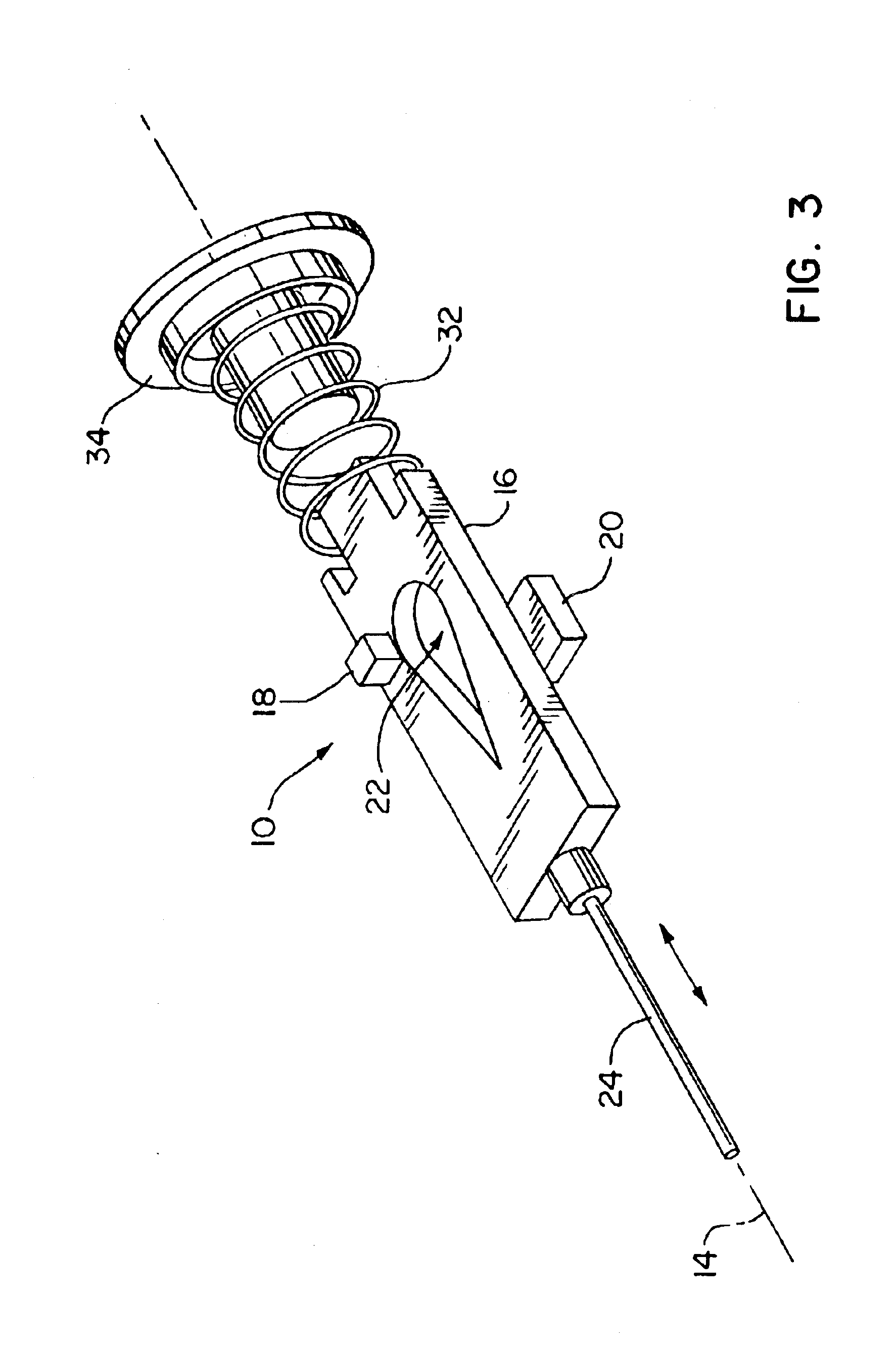
[0019]FIG. 3 is an exploded perspective view of the internal elements of a position sensor 10 having some differences, as explained below, from the sensor 10 of FIGS. 1 and 2. The same reference numerals are used for similar elements in the following descriptions of the first and second exemplary embodiments, as shown in FIGS. 1-3.

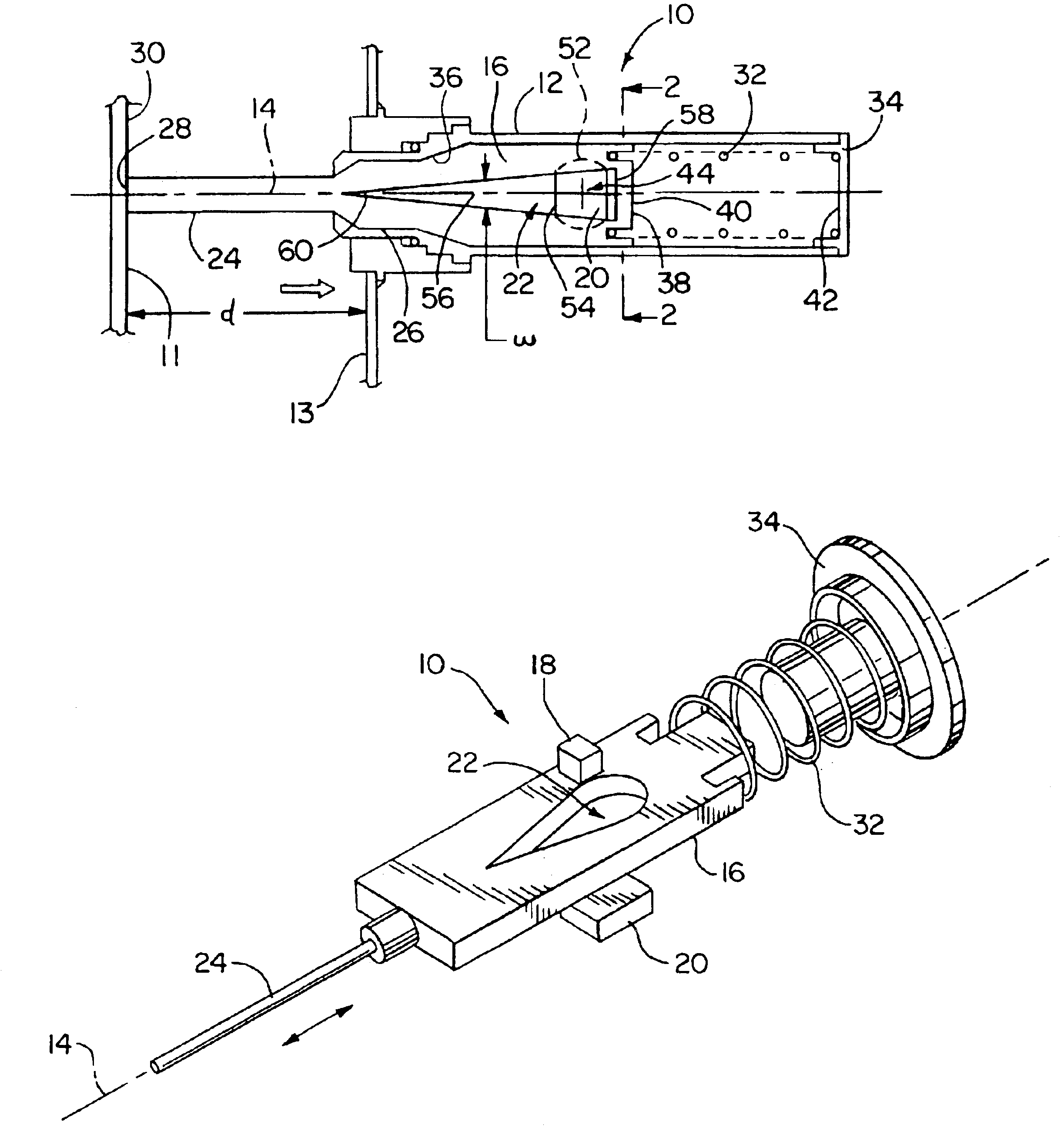
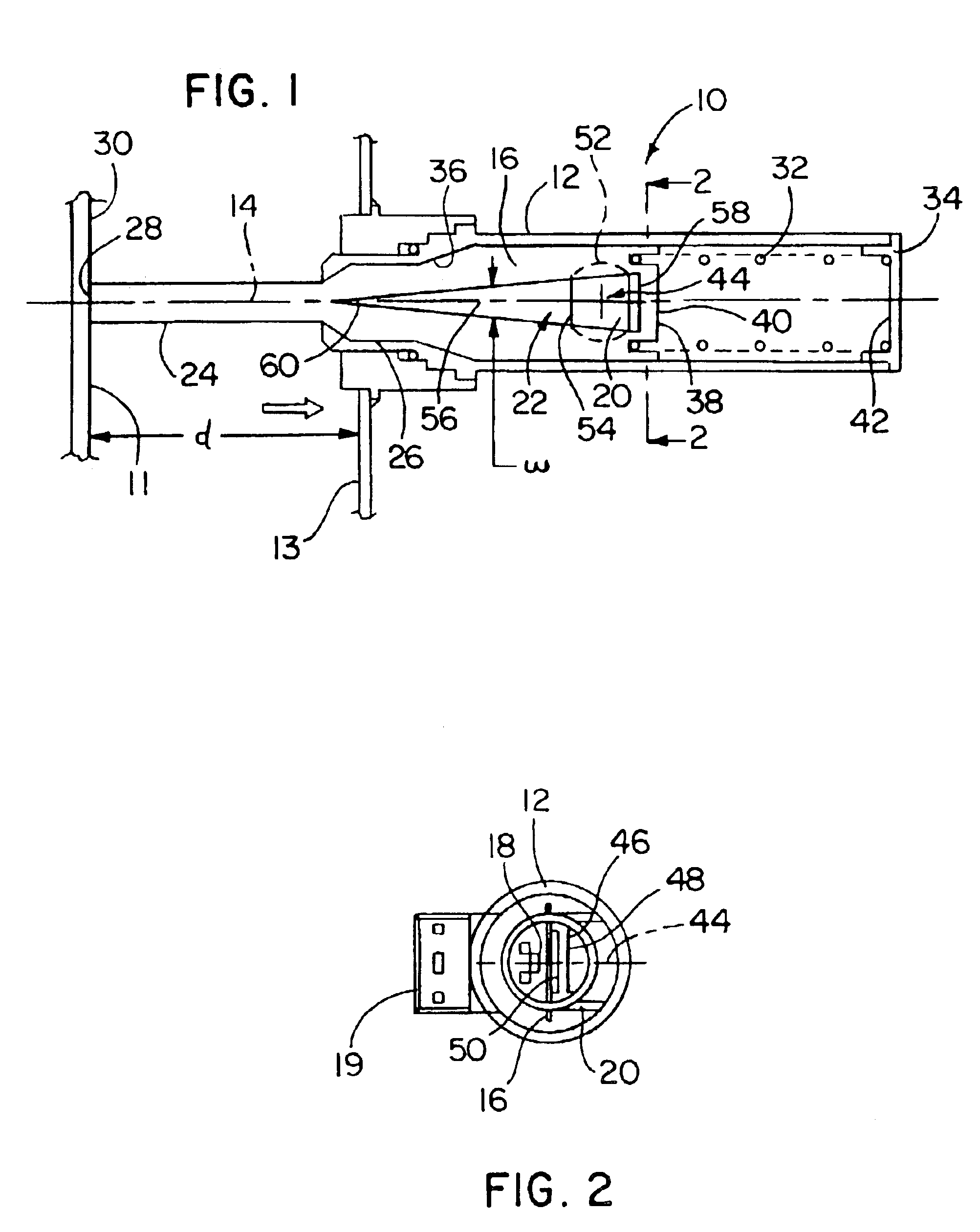
[0020]The movable element is configured as a vane 16 of ferromagnetic material mounted in the housing 12 for sliding movement along the axis of motion 14. The vane 16 includes an aperture 22 extending through the vane 16 in a direction transverse to the axis of motion 14. A connection, in the form of pin 24, extends from a first axial end 26 of the vane 16 and out of the housing 12 for receiving a positional input from a point of contact 28 with a surface 30 of a translating wall 11 external to the sensor 10.

[0021]The sensing element 18 is fixedly attached to the housing 12 adjacent one side of the vane 16 for sensing magnetic flux passing through the aper...

first embodiment

[0024]As shown in FIG. 3, the magnet 20 of the second exemplary embodiment of a linear position sensor 10 has a flat planar body with a periphery that is rectangular, rather than circular as is the case for the magnet 20 of the first embodiment shown in FIGS. 1 and 2. The shape of the magnet 20 has an effect on the linearity of an output signal generated by the sensing element 18, and can be judiciously selected to fine tune the performance of the position sensor 10 in a manner that is desirable for various embodiments of our invention.

[0025]The aperture 22 in the vane 16 has a width ‘w’ transverse to the axis of motion 14 that varies along the axis of motion 14. The width ‘w’ can vary in either a linear or a non-linear manner along the axis of motion 14, to allow the intensity of the magnetic flux passing through the aperture from the magnet 20 to the sensing element 18 to vary in relation to the position ‘d’ in a manner that produces a desired relationship between the position ‘d’...


PUM


Abstract

An apparatus and method are provided for sensing the position of a point of contact through use of a sensor having a movable element, disposed between a sensing element and a source of magnetic flux, and having an aperture therein for allowing a portion of the magnetic flux from the source of magnetic flux to pass through the aperture and impinge on the sensing element. The aperture may have various shapes to provide a desired linear or non-linear relationship between the position of the movable element and the intensity of the flux that passes through the aperture and impinges on the sensing element for a given position of the movable element.

Description

TECHNICAL FIELD OF THE INVENTION[0001]This invention relates to sensing the position of a surface or a datum, and more particularly to position sensors that determine the position and / or motion of a point of contact in relation to the position sensor by detecting the intensity of magnetic flux impinging on a sensing element within the position sensor.BACKGROUND OF THE INVENTION[0002]In many mechanical devices, it is desirable or necessary to detect the position or movement of a movable member of the device in relation to another part of the mechanical device. It is also desirable in some cases to provide an output electrical signal that is indicative of the current position or movement of the movable member.[0003]One example of such a mechanical device is a brake booster for a vehicle, in which it is desirable to know the position of a movable diaphragm support located inside of the booster, in relation to a housing of the booster that completely encloses the diaphragm support and m...

Claims


Application Information

Patent Timeline
Patent Type & Authority Patents(United States)
IPC IPC(8): B60T13/52B60T13/569B60T17/22B60T17/18G01D5/14G01D5/12
CPCB60T13/569G01D5/147B60T17/22G01D2205/775
Inventor GREEN, ALAN H.QUINTANA, MANUEL A.
Owner DELPHI TECH INC
Why Eureka
Try Eureka