Modulated power supply

a power supply and module technology, applied in the direction of amplifiers with only semiconductor devices, dc amplifiers with modulators/demodulators, amplifiers with semiconductor devices/discharge tubes, etc., can solve the problems of consuming a large quantity of power, requiring expensive power devices, and low efficiency, so as to achieve the effect of minimising switching losses

Inactive Publication Date: 2005-05-17
MALIKIE INNOVATIONS LTD
View PDF3 Cites 22 Cited by
  • Summary
  • Abstract
  • Description
  • Claims
  • Application Information

AI Technical Summary

Benefits of technology

[0012]It has been realised that, during normal operation, only some of the switching devices need to be operated. By operating only some of the switching devices during the time that low signal amplitudes are present, there is a reduction in switching losses in comparison to operating the full array of switches. This reduces the overall power consumption of the power supply. This apparatus is particularly well-suited to signals which, in the time domain, have occasional extreme peaks or troughs but usually have an amplitude lying within a narrower band, so called ‘peaky’ signals.
[0015]The controller can be arranged to maintain the secondary power switching device in a continuously on state (100% duty cycle) during the periods when the input signal lies outside the first predetermined range. This minimises switching losses in the secondary power switching device and the number of switching transients which would otherwise result from operating the secondary power switching device in a pulse width modulated manner. A desired output level can be achieved by operating the primary power switching device in a manner which subtracts an unwanted portion of the output level.

Problems solved by technology

While linear power amplifiers operate in a generally linear manner they are known to have a disadvantage of achieving low efficiency.
In high power applications, such as the transmit chain of a wireless base station, this requires expensive power devices which consume a considerable quantity of power and require large heatsinks and associated cooling equipment to maintain them at an optimum operating state.
Switching devices have a finite frequency range over which they can be reliably operated, and begin to work in a non-ideal manner when operated towards the extremes of their operating range.
For an input signal having a wide bandwidth, this requirement forces the switching device to operate in the region towards the upper boundary of its operating range, which incurs switching losses and begins to cause non-ideal behaviour.
During signal troughs the current demand is low which reduces the negative slew rate capability of the supply and can cause a conventional PWM converter to go into discontinuous operation.

Method used


Image

  • Modulated power supply
  • Modulated power supply
  • Modulated power supply

Examples


Embodiment Construction

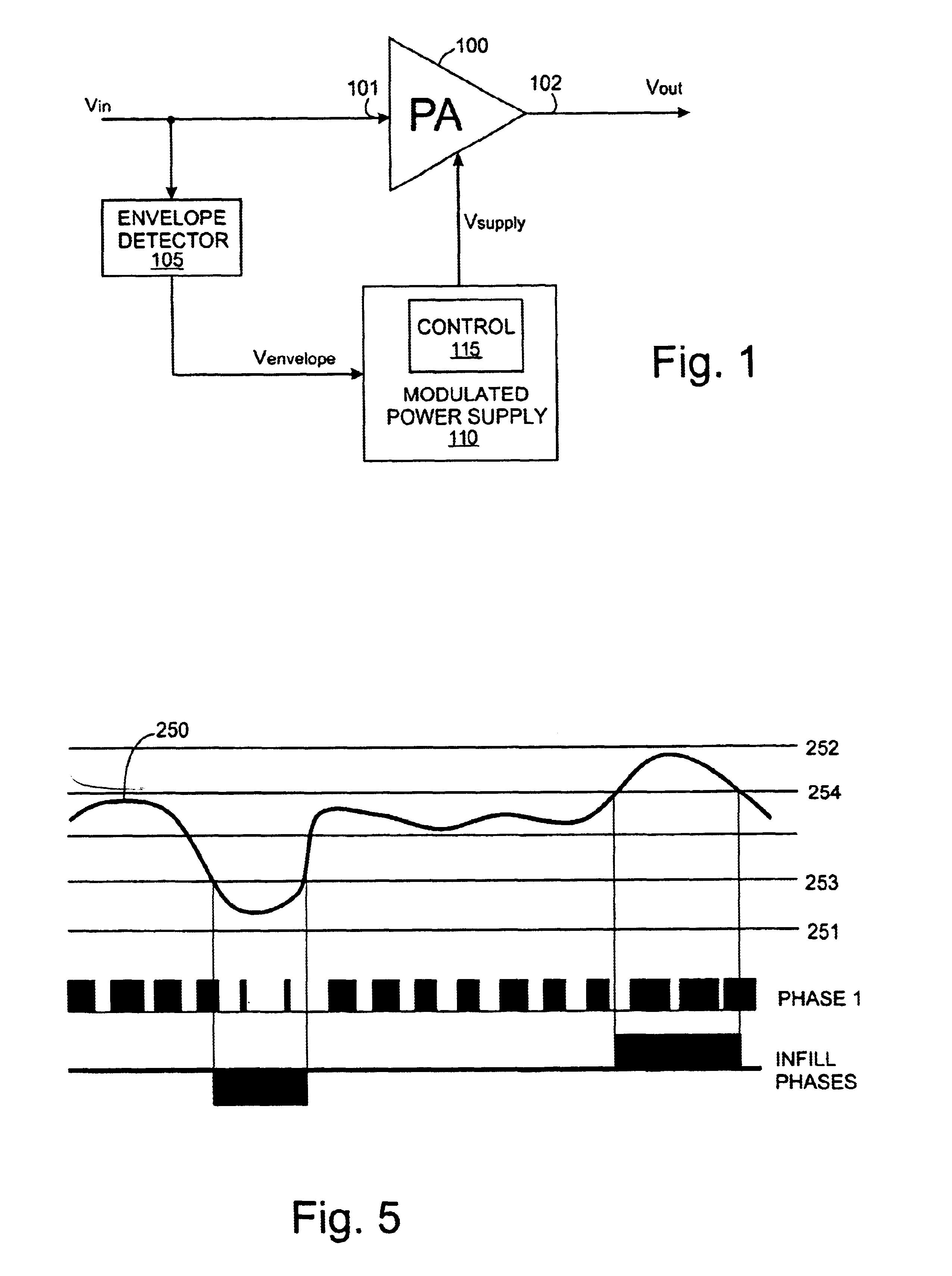
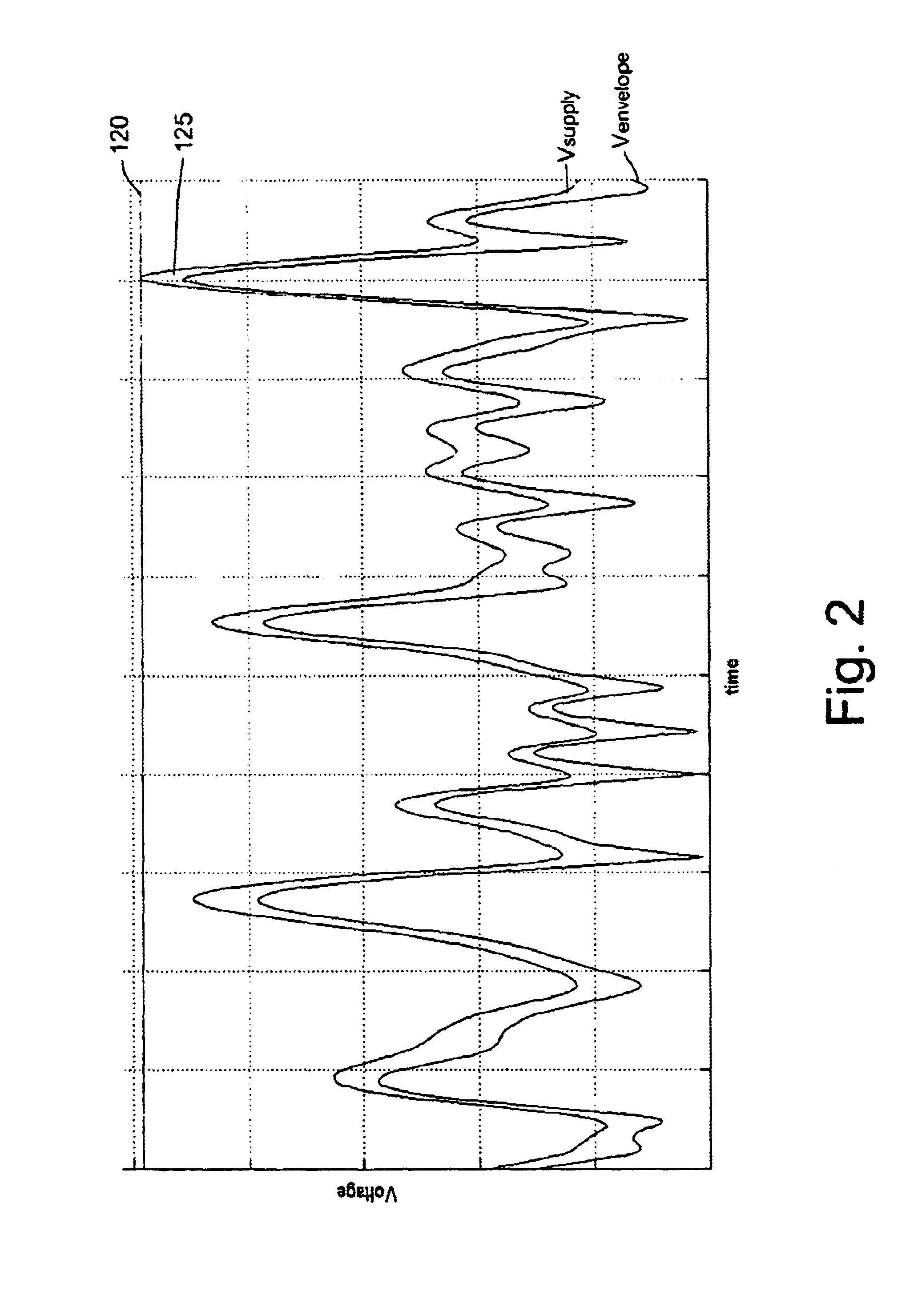
[0033]Before describing the invention in detail, FIG. 1 shows a power amplifier arrangement comprising a power amplifier 100 and a modulated power supply 110. An input signal, which is to be amplified by the power amplifier 100, is also applied to an envelope detector 105. A signal, Venvelope, representing the envelope of the input signal is applied to an input of the modulating power supply 110. A control circuit 115 within the modulating power supply 110 receives the input signal and determines appropriate control signals which cause the power supply 110 to generate a supply voltage Vsupply which substantially tracks the envelope of the input signal Vin. The input signal Vin may also be applied to a pre-distortion module (not shown) before being applied to the input to the power amplifier 100. FIG. 2 shows the operation of the power supply over a period of time, showing the envelope of the input signal Venvelope and the envelope of the dynamically modulated power supply voltage Vs...


PUM


Abstract

A modulated power supply comprises a converter having a primary power switching device and a secondary power switching device. The outputs of the primary and secondary power switching devices are combined to provide an output. A controller controls operation of the switching devices in response to a modulating input signal. Only the primary power switching device is operated while a property of the input signal lies within a first predetermined range and both the primary and the secondary power switching devices are operated while the property of the input signal lies outside the first predetermined range. This can reduce switching losses in comparison to operating the full array of switches. This is particularly well-suited to peaky signals. The property of the modulating input signal which causes the controller to bring secondary power switching devices into operation can be amplitude or rate of change of amplitude.

Description

FIELD OF THE INVENTION[0001]This invention relates to modulated power supplies.BACKGROUND TO THE INVENTION[0002]In the field of power applications, it is common to use linear power amplifiers. While linear power amplifiers operate in a generally linear manner they are known to have a disadvantage of achieving low efficiency. In high power applications, such as the transmit chain of a wireless base station, this requires expensive power devices which consume a considerable quantity of power and require large heatsinks and associated cooling equipment to maintain them at an optimum operating state.[0003]In order to increase the efficiency of a linear power amplifier, it is known to modulate the power supply to the linear power amplifier with the envelope of the signal which is to be amplified. The power supply can be a Pulse Width Modulated (PWM) power supply in which a power switching device, such as a power transistor, is turned on and off at a high frequency, with the width of the ...

Claims


Application Information

Patent Timeline
Patent Type & Authority Patents(United States)
IPC IPC(8): H03F1/02
CPCH03F1/0222H03F2200/331
Inventor DOLMAN, GRAHAM
Owner MALIKIE INNOVATIONS LTD
Why Eureka
Try Eureka