Method for constructing a photomask assembly using an encoded mark

a technology of encoded marks and photomasks, applied in the field of photolithography, can solve the problems of reducing the amount of light transmitted through the photomask, pellicle deformation, and affecting the quality of the photomask, and achieve the effect of avoiding the disadvantages and problems of constructing and using the photomask assembly

Inactive Publication Date: 2005-05-17
TOPPAN PHOTOMASKS INC
View PDF6 Cites 27 Cited by
  • Summary
  • Abstract
  • Description
  • Claims
  • Application Information

AI Technical Summary

Benefits of technology

[0009]In accordance with the teachings of the present invention, the disadvantages and problems associated with constructing and using a photomask assembly in a lithography process have been substantially reduced or eliminated. In a particular embodiment, a method constructing a photomask assembly includes mounting a pellicle on a photomask if at least one of the symbols of a first encoded mark matches at least one of the symbols of a second encoded mark.
[0014]Another important technical advantage of certain embodiments of the present invention includes an encoding system that reduces errors during construction of a photomask assembly. A potential error exists during construction of a photomask assembly by improperly orientating the pellicle on the photomask. To aid in construction of a photomask assembly, encoding marks may be used to identify the proper alignment for the pellicle to the photomask. Being able to match and align encoding marks on photomask components permits the correct construction of a photomask assembly.
[0015]A further important technical advantage of certain embodiments of the present invention includes an encoding system that reduces manufacturing errors based on an incompatible photomask assembly. Incorporating the encoding marks on photomask components allows for constant monitoring of the compatibility of components. As part of this monitoring process, a photomask assembly may be inspected to determine that the assembly has been constructed according to the correct specifications for a particular semiconductor process. A photomask assembly used in the wrong semiconductor process may cause damage to a semiconductor IC chip being created from the photomask assembly.

Problems solved by technology

Since a photomask is used to project this image and any defect on the surface of the photomask will result in a transferred imperfection onto the wafer, any defect on the surface of the photomask could possibly render the wafer useless.
The use of a pellicle with an incorrect wavelength may cause the pellicle to degrade, which can reduce the amount of light transmitted through the photomask and affect a pattern projected on a wafer.
Even if a pellicle and a photomask are correctly assembled, a problem may still exist if a photomask assembly, which includes a photomask and a pellicle, is placed in the wrong lithography tool.
Although DUV pellicles can be used in I-line applications, the cost of DUV pellicles greatly outweighs the benefit of this generic feature.
Conversely, inexpensive I-line membrane pellicles used at DUV wavelengths will rapidly degrade and ultimately corrupt the printed image on a wafer.
This technique suffers from several opportunities for human error.
Any lapse in concentration or error in the part number list may result in the improper combining of photomask assemblies for a manufacturing process, which may cause costly mistakes.
Using this different part numbering system for each photomask component may result in improper combining of photomask assemblies for a manufacturing process, which may further cause costly mistakes.

Method used


Image

  • Method for constructing a photomask assembly using an encoded mark
  • Method for constructing a photomask assembly using an encoded mark
  • Method for constructing a photomask assembly using an encoded mark

Examples


Embodiment Construction

[0026]Preferred embodiments of the present invention and their advantages are best understood by reference to FIGS. 1 through 7, where like numbers are used to indicate like and corresponding parts.

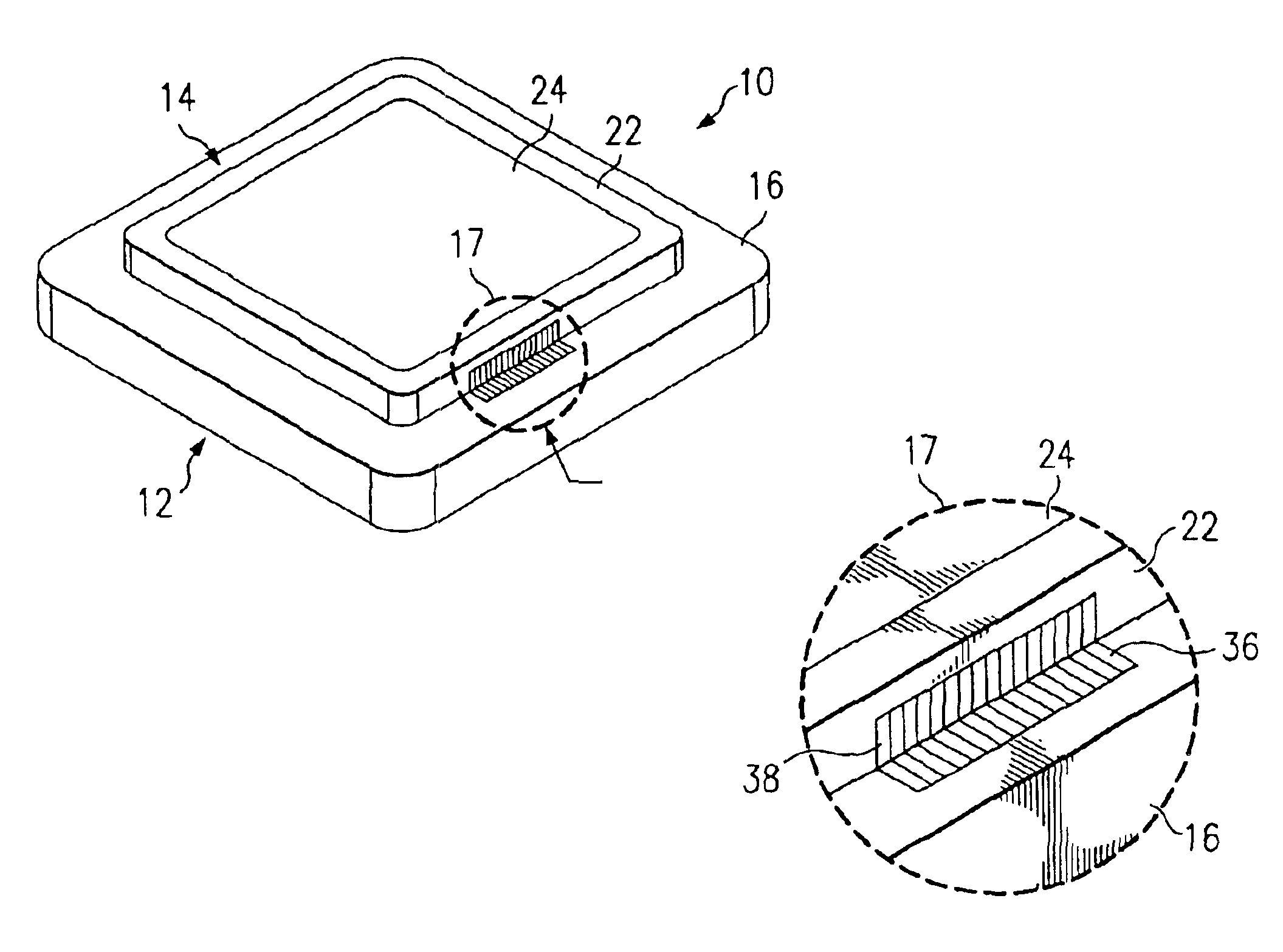
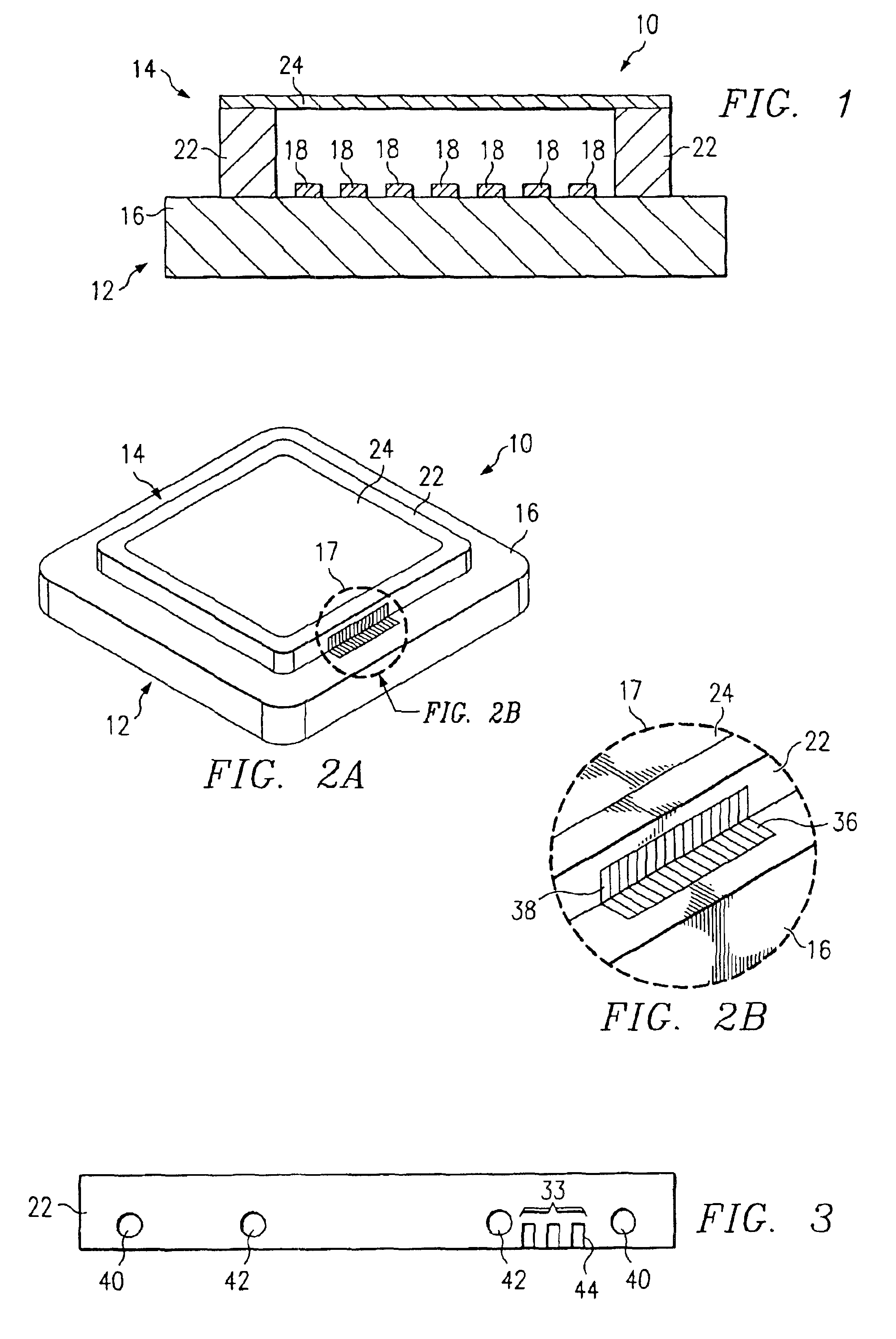
[0027]FIG. 1 illustrates a cross-sectional view of photomask assembly 10. In the illustrated embodiment, photomask assembly 10 includes photomask 12 coupled to pellicle 14. Substrate 16 and patterned layer 18 form photomask 12, otherwise known as a mask or reticle. Photomask 12 may have a variety of sizes and shapes, including but not limited to round, rectangular, or square. Photomask 12 may also be any variety of photomask types, including, but not limited to, a one-time master, a five-inch reticle, a six-inch reticle or a nine-inch reticle. Photomask 12 may further be a binary mask, a phase shift mask, or any other type of mask suitable for use in a lithography system.

[0028]Substrate 16 may be a transparent material such as quartz, synthetic quartz, fused silica, magnesium fluoride (Mg...


PUM

PropertyMeasurementUnit
exposure wavelengthsaaaaaaaaaa
exposure wavelengthaaaaaaaaaa

Abstract

A method for constructing a photomask assembly using an encoded mark is disclosed. The method includes comparing a first encoded mark located on a photomask with a second encoded mark located on a pellicle. The first encoded mark includes one or more first symbols and the second encoded mark includes one or more second symbols. The method further includes mounting the pellicle on the photomask if at least one of the symbols of the first encoded mark matches at least one of the symbols of the second encoded mark.

Description

CROSS REFERENCE TO RELATED APPLICATION[0001]This application claims priority from U.S. Provisional Patent Application Ser. No. 60 / 279,062 filed Mar. 27, 2001, and entitled “Unique Mask and Pellicle Quality Assurance Encoding Scheme to Manage and Confirm Accurate Material Assembly Requirement.”TECHNICAL FIELD OF THE INVENTION[0002]This invention relates in general to photolithography, and more particularly to a method of constructing a photomask assembly using an encoded mark.BACKGROUND OF THE INVENTION[0003]Photomasks, commonly referred to as masks or reticles, are used in the manufacture of semiconductor integrated circuits (ICs). Typically, a photomask is made of an opaque patterned layer applied on a transparent substrate. By exposing the photomask to a particular wavelength of light in a photolithographic process, an image is projected through the photomask onto a semiconductor wafer creating an imprint of the patterned layer on the wafer.[0004]Since a photomask is used to proje...

Claims


Application Information

Patent Timeline
Patent Type & Authority Patents(United States)
IPC IPC(8): G03B27/62G03F1/14
CPCG03F1/64G03F1/38
Inventor WEST, CRAIG A.STORM, GLENN EDWARDMACDONALD, SUSAN S.GORDON, JOSEPH S.CARROLL, III, JAMES A.
Owner TOPPAN PHOTOMASKS INC
Why Eureka
Try Eureka