Stimulation/sensing lead adapted for percutaneous insertion

a percutaneous insertion and electrode array technology, applied in the field of electrode array adaptability, can solve the problem of not offering an opportunity for electrode array variance, and achieve the effect of enhancing the flexibility of such lead and enhancing the steerability of such lead

Inactive Publication Date: 2005-05-17
ADVANCED NEUROMODULATION SYST INC
View PDF16 Cites 220 Cited by
  • Summary
  • Abstract
  • Description
  • Claims
  • Application Information

AI Technical Summary

Benefits of technology

[0019]Another object of the present invention is to provide a paddle-type lead that includes certain features to increase the flexibility of such lead, thus enhancing the steerability of such lead.

Problems solved by technology

While laminotomy leads are likely more stable during use, these leads do not offer an opportunity for electrode array variance as the configuration of such arrays are fixed.

Method used


Image

  • Stimulation/sensing lead adapted for percutaneous insertion
  • Stimulation/sensing lead adapted for percutaneous insertion
  • Stimulation/sensing lead adapted for percutaneous insertion

Examples


Embodiment Construction

[0040]Various embodiments, including preferred embodiments, will now be described in detail below with reference to the drawings.

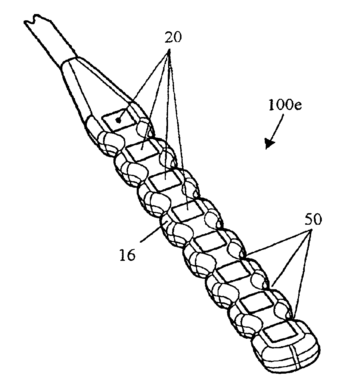
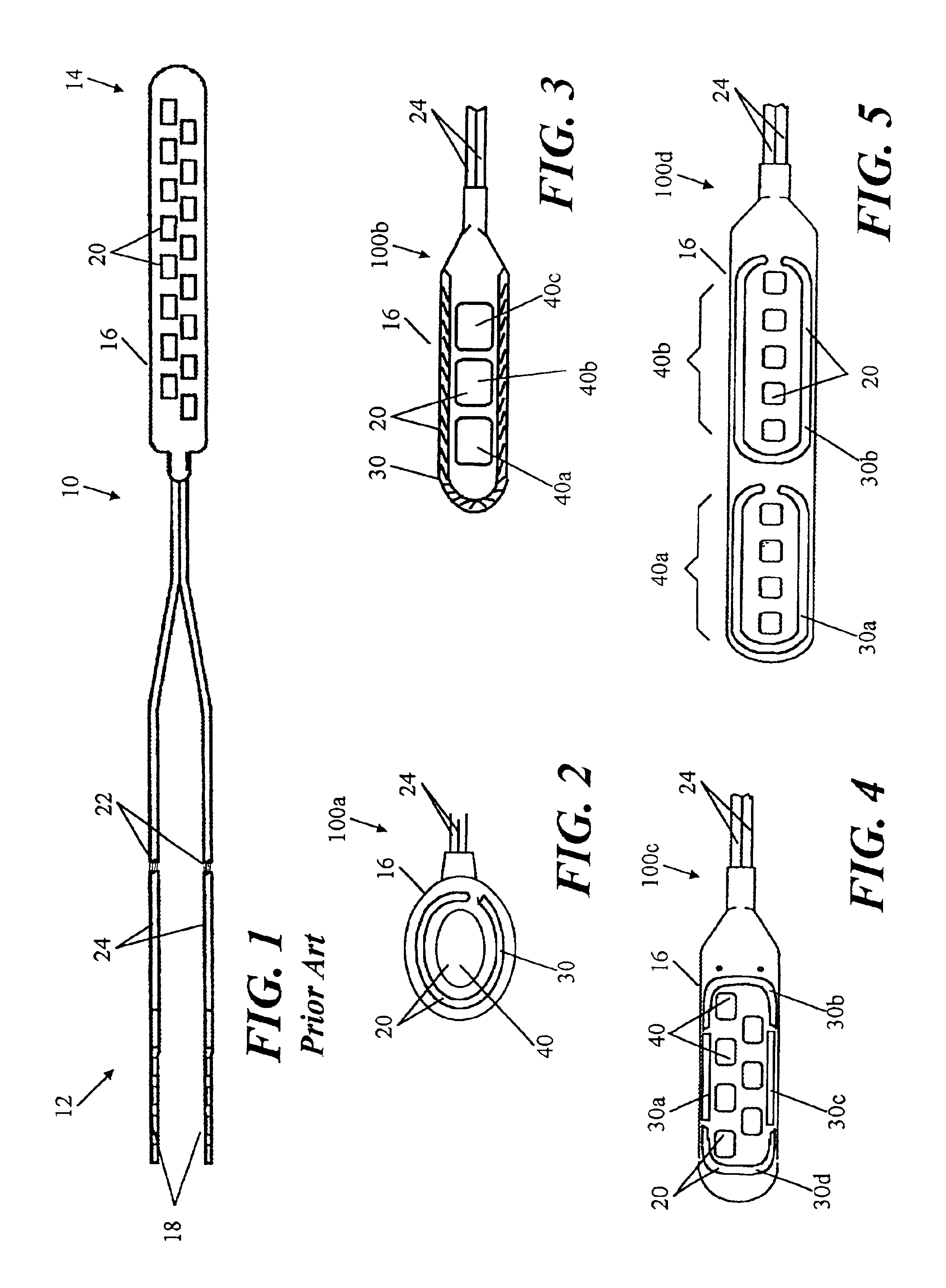
[0041]In reference to FIG. 1, the illustrated laminotomy lead 10 includes a proximal end 12 and a distal end 14. The proximal end 12 includes a plurality of electrically conductive terminals 18, and the distal end 14 includes a plurality of electrically conductive electrodes 20 arranged within a flat, thin paddle-like structure 16. Typically, each terminal 18 is electrically connected to a single electrode 20 via a conductor 22; however, a terminal 18 can be connected to two or more electrodes 20.

[0042]Terminals 18 and electrodes 20 are preferably formed of a non-corrosive, highly conductive material. Examples of such material include stainless steel, MP35N, platinum, and platinum alloys. In a preferred embodiment, terminals 18 and electrodes 20 are formed of a platinum-iridium alloy.

[0043]The sheaths 24 and the paddle structure 16 are formed from a medica...


PUM


Abstract

The present invention relates to a percutaneous insertion-capable lead, wherein insertion is made through a percutaneous insertion structure. For one embodiment of such lead, the electrode-supporting stimulation portion of the lead includes at lease one waisted region, relative to a transverse dimension of the lead, to facilitate lead steerability.

Description

RELATED APPLICATION[0001]This application is a continuation-in-part of U.S. patent application Ser. No. 09 / 635,910, filed Aug. 10, 2000, now pending.FIELD OF THE INVENTION[0002]The present invention relates to an epidural stimulation lead, and in particular, to an epidural stimulation lead adapted for percutaneous insertion.BACKGROUND OF THE INVENTION[0003]Application of specific electrical fields to spinal nerve roots, spinal cord, and other nerve bundles for the purpose of chronic pain control has been actively practiced since the 1960s. While a precise understanding of the interaction between the applied electrical energy and the nervous tissue is not fully appreciated, it is known that application of an electrical field to spinal nervous tissue (i.e., spinal nerve roots and spinal cord bundles) can effectively mask certain types of pain transmitted from regions of the body associated with the stimulated tissue. More specifically, applying particularized electrical energy to the ...

Claims


Application Information

Patent Timeline
Patent Type & Authority Patents(United States)
IPC IPC(8): A61N1/05A61B5/042
CPCA61B5/0422A61B5/6852A61N1/0553A61B17/3468A61B17/3401A61B5/287
Inventor ERICKSON, JOHN H.DREES, SCOTT F.DAGLOW, TERRYMUNSON, JR., JOHN CONNELL
Owner ADVANCED NEUROMODULATION SYST INC
Why Eureka
Try Eureka