Cleaning apparatus

a technology of cleaning apparatus and airflow, which is applied in the direction of application, dispersed particle filtration, and using liquid separation agents, can solve the problems of low airflow weight loading and other problems, and achieve the effect of preventing the transfer of heavier parts and improving the retention of lighter parts

Inactive Publication Date: 2005-05-24
ARNOLD ADRIAN CHRISTOPHER +1
View PDF16 Cites 108 Cited by
  • Summary
  • Abstract
  • Description
  • Claims
  • Application Information

AI Technical Summary

Benefits of technology

[0010]The means for generating a primary vortex in the particulate-containing airstream entering the housing may comprise an array of vanes upstream of the housing, individual vanes being optionally spaced apart axially to prevent clogging by large particulates or filamentary material, or an off-center, for example, tangential, inlet pipe. An auxiliary air intake may provide a laminar film or layer of dirt-free air at the periphery of the primary chamber across or at least into the interconnection means, to i...

Problems solved by technology

The fact that the air in the cyclone part of the apparatus has had the denser p...

Method used


Image

  • Cleaning apparatus
  • Cleaning apparatus
  • Cleaning apparatus

Examples


Embodiment Construction

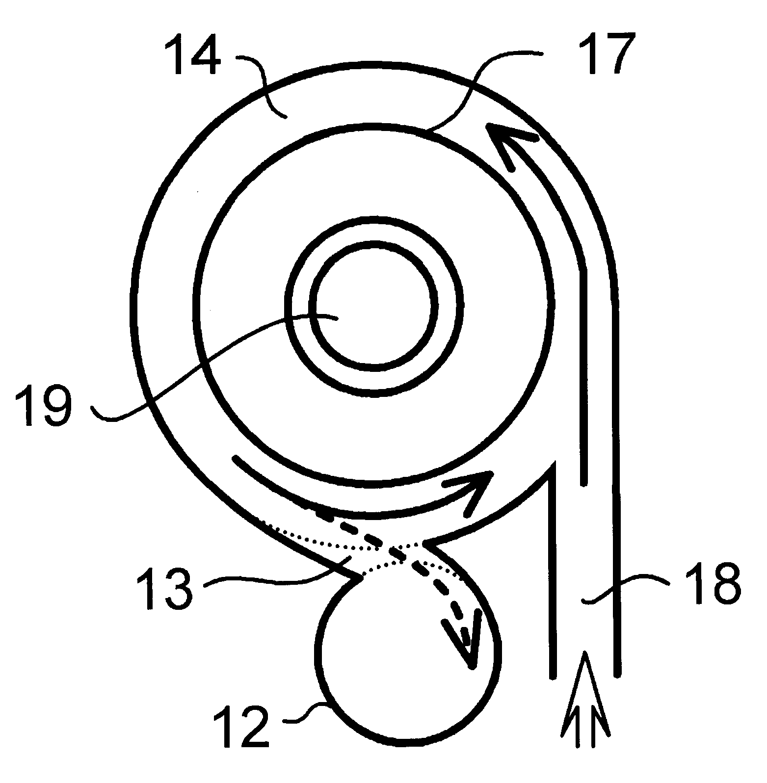
[0022]Referring to FIGS. 1 and 2, the apparatus consists of a primary chamber 11 and a secondary chamber 12 joined by a generally chordal interconnection neck 13, the walls of which are constituted by respective wall portions of the primary and secondary chamber being tangentially deformed and joined to the other chamber. The primary chamber 11 has an upper cylindrical portion 14 and a lower co-axial cyclone separator 15. An inner flange 16 is disposed between the upper and lower parts; the flange has an upwardly-turned inner peripheral lip 17. The flange 16 is not essential.

[0023]A tangential inlet 18 is provided at the upper end and also an axial outlet 19 for exhaust air; an electric motor (not shown) draws air through the apparatus, or alternatively may blow air through under positive pressure.

[0024]Removable collection vessels 20, 21 are provided to the cyclone separator and secondary separation chamber respectively. As shown by the arrows, inlet air is constrained by the outle...


PUM

PropertyMeasurementUnit
Flow rateaaaaaaaaaa
Diameteraaaaaaaaaa
Radiusaaaaaaaaaa

Abstract

Apparatus for separating particulate matter from an airstream includes a housing including an intake for particulates-containing air and an exhaust for cleaned air, in which the apparatus includes a primary vortex generator in the intake air and the housing includes a separation zone which includes primary and secondary separation chambers each associated with respective particulates collector and including an interconnector adapted to generate a secondary vortex in the secondary separation chamber.

Description

[0001]This is a continuation of International Application No. PCT / GB99 / 00507, having a filing date of Feb. 18, 1999, now abandoned, which is a continuation of Great Britain application no. GB9803539.7, having a filing date of Feb. 19, 1998, now abandoned.TECHNICAL FIELD[0002]This invention relates to a cleaning apparatus of the type for separating particulate matter from a fluid stream such as an airstream, which are used, for example, in so-called bagless vacuum cleaners.BACKGROUND OF THE INVENTION[0003]Patent Cooperation Treaty Publication WO 96 / 11047 describes apparatus for the removal of particulate material suspended in a gas stream, in which rotary motion is generated in the stream which is then passed to an expansion chamber where the gases are decelerated to enable particulates to fall out of suspension and to be collected in a collection chamber. It has been found that, whereas such apparatus deals effectively with large and medium-sized particles, small particles tend to r...

Claims


Application Information

Patent Timeline
IPC IPC(8): B01D45/12A47L9/16B01D45/16B04C5/081B04C5/14B04C5/185B04C5/26
CPCA47L9/1608A47L9/1683B01D45/16B04C5/14B04C5/185B04C5/26B04C5/081Y10S55/14
Inventor ARNOLD, ADRIAN CHRISTOPHERARNOLD, ARTHUR JOHN
Owner ARNOLD ADRIAN CHRISTOPHER
Why Eureka
Try Eureka