Electrolysis cell and internal combustion engine kit comprising the same

a technology of electrolysis cell and internal combustion engine, which is applied in the field of electrolysis cell, can solve the problems of affecting the acceptance of an otherwise highly desirable technology, affecting causing an explosion, etc., and achieves the effects of improving the combustion efficiency of the internal combustion engine, simple operation, and minimal operator attention and maintenan

Inactive Publication Date: 2005-05-24
CANADIAN HYDROGEN ENERGY CO LTD
View PDF83 Cites 53 Cited by
  • Summary
  • Abstract
  • Description
  • Claims
  • Application Information

AI Technical Summary

Benefits of technology

[0015]Most particularly, the device should produce hydrogen and oxygen gas in sufficient quantity to improve the combustion efficiency of the internal combustion engine to which it is connected. The device should deliver the generated gases effectively and consistently to the engine, so that the benefits of the gases as a fuel additive are realized. Preferably, the device will work with different types of engines, and particularly with turbocharged diesel engines typically used by commercial trucks that are heavy users of fuel. It would be advantageous if it could provide the gas throughout the duration of a trip without disruption, and in any weather condition which the vehicle may be expected to encounter, including both freezing winter and hot summer temperatures.
[0016]The device should be simple to operate, requiring minimal operator attention and maintenance. Preferably, the device should require little more than an occasional water refill. It would also be advantageous for the device to be constructed from components that are relatively simple and durable, so that breakdowns will be infrequent and servicing straightforward to perform. Yet another advantage would be for the device to be easy to install in a vehicle, without requiring extensive engine modification.
[0017]In any gas apparatus there is inevitably a risk of blockages developing in the gas circulation system, leading to a rise in pressure and an explosion. Since the device of the present invention is used in motor vehicles that contain highly flammable hydrocarbon fuel and one or more people in close proximity, a gas explosion could cause serious harm and undermine acceptance of an otherwise highly desirable technology. Accordingly, it is important that the device be designed to minimize this risk as much as possible. The device therefore should preferably include venting features to relieve gas pressure before it has a chance to build up to dangerous levels. Further, it would be especially advantageous if in the unlikely event of the venting features failing or of a spark being introduced, the structure of the device itself could contain the ensuing explosion, so that the risk of harm to the vehicle occupants would be measurably reduced.
[0018]The electrolysis cell of the present invention uses electrodes constructed of expanded nickel to generate gas, and includes a region designated as an electrolytic fog. A fan and condenser help lower the temperature of the gas and reduce moisture. The electrolysis is further enhanced by regulating the power input to the cell. In this way the device of the present invention produces an adequate supply of gas to aid combustion. The device delivers the gas to the engine under pressure, thereby ensuring a constant flow even when the air intake pressure is high due to turbocharger boost. The gases are continuously available, aided by a separate on-board water supply that automatically replenishes the cell when needed. The device contains both heating and cooling features that enable gas to be generated in extreme weather conditions. The only operator maintenance required is to occasionally refill the water supply. Even under commercial driving conditions, only one refill approximately every 3-4 weeks should be sufficient. The cell and kit are made of sturdy and simple components, with no moving parts or complicated electronics, so that breakdowns are infrequent and service costs minimized. Further, the device readily connects with existing engines. Power is received from the vehicle battery, and the output gas hose simply attaches to a standard input at the air intake manifold. The device includes overlapping safety venting features to relieve internal gas pressure if the pressure rises above standard operating levels. Further, the device is built to pressure vessel standards so that in the unlikely event that an explosion occurs, it will be contained and less likely to cause actual harm.

Problems solved by technology

In any gas apparatus there is inevitably a risk of blockages developing in the gas circulation system, leading to a rise in pressure and an explosion.
Since the device of the present invention is used in motor vehicles that contain highly flammable hydrocarbon fuel and one or more people in close proximity, a gas explosion could cause serious harm and undermine acceptance of an otherwise highly desirable technology.

Method used


Image

  • Electrolysis cell and internal combustion engine kit comprising the same
  • Electrolysis cell and internal combustion engine kit comprising the same
  • Electrolysis cell and internal combustion engine kit comprising the same

Examples


Embodiment Construction

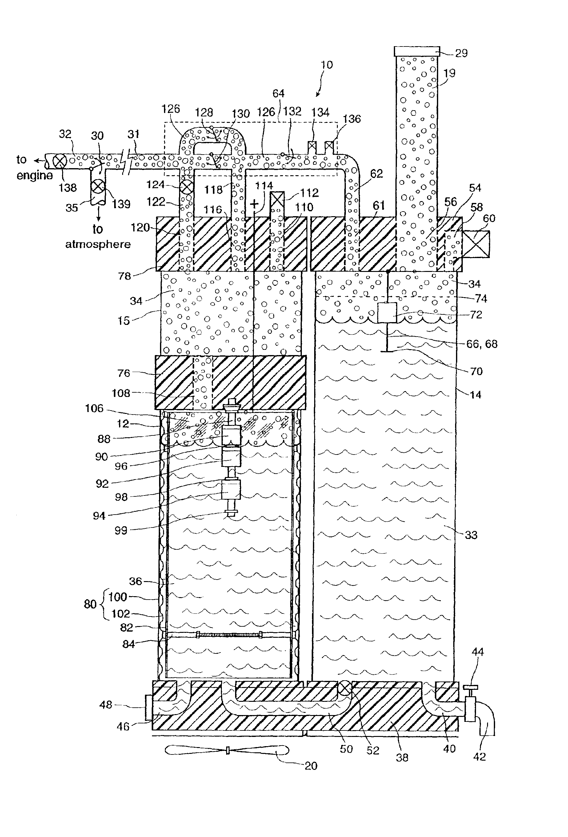
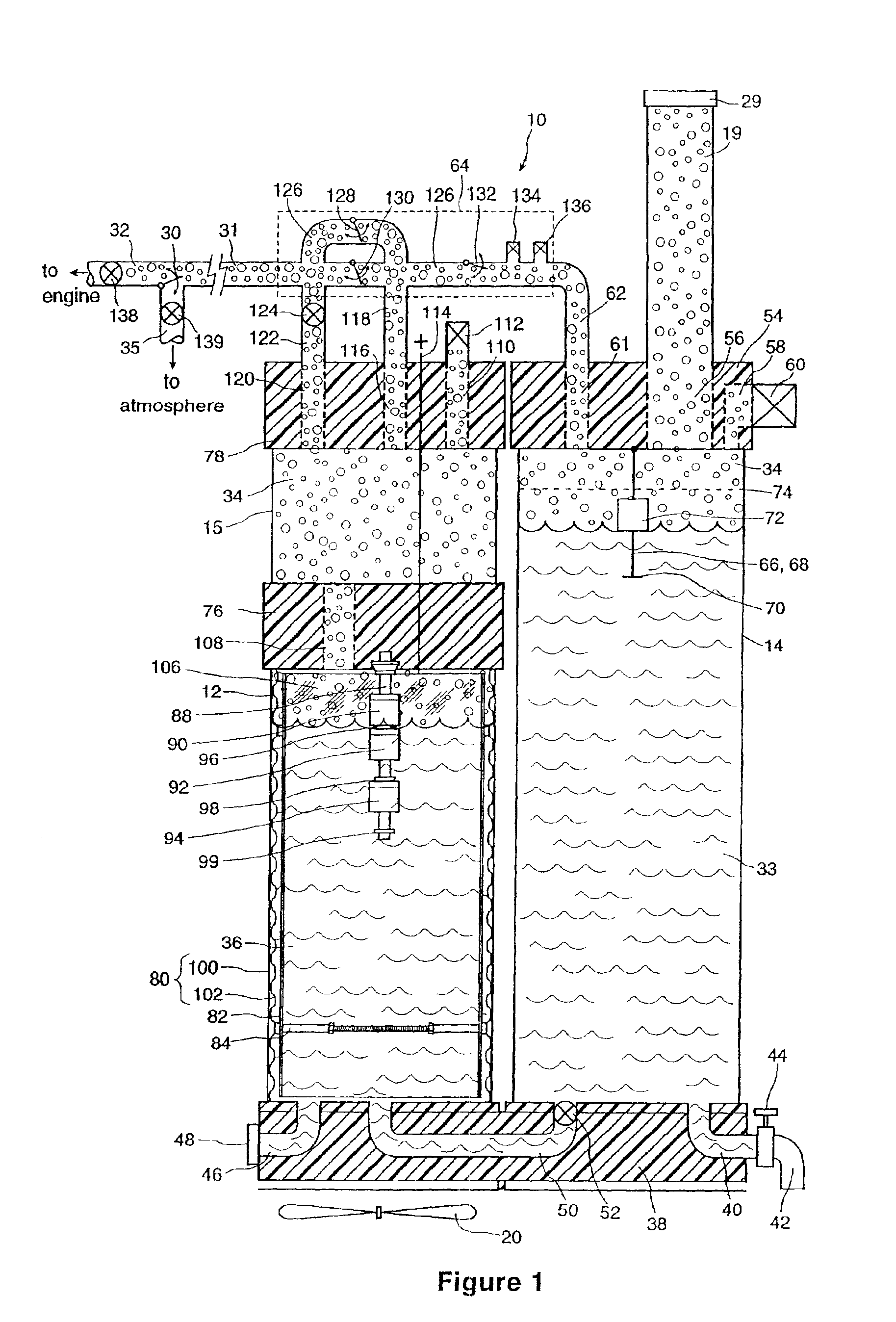
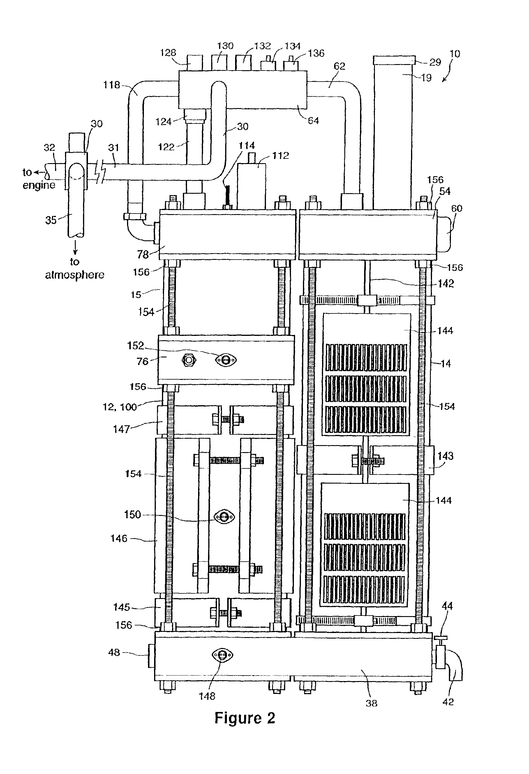
[0031]The present invention is for a system comprising an electrolysis cell and associated kit that generates and delivers a gas that acts as a fuel additive for an internal combustion engine. Electrolysis is a well known process whereby an electrical current is passed through a water-based solution. The current splits the water molecules, releasing hydrogen and oxygen gases which can be directed to the engine. The gases are injected into the engine at the air intake, where they enhance combustion of the hydrocarbon fuel used by the engine.

[0032]The invention finds particular application with motor vehicles that are powered by internal combustion engines. The invention may be used with a variety of vehicles and fuels, including conventional passenger cars having gasoline engines, commercial trucks that use diesel engines and turbochargers, as well as specialized vehicles such as forklifts or tractors that may be powered by less common fuels such as propane, methane, or natural gas. ...


PUM

PropertyMeasurementUnit
heightaaaaaaaaaa
heightaaaaaaaaaa
lengthaaaaaaaaaa

Abstract

A system for producing one or more gases for enhancing combustion in an internal combustion engine, the engine having an intake, the system comprising: an electrolysis cell, for generating one or more combustion enhancing gases under pressure; a gas conduit, for connecting the electrolysis cell to the internal combustion engine; and a flow regulator, operatively connected between the electrolysis cell and the intake of the engine, for regulating a flow of the combustion enhancing gases to the engine.

Description

CROSS-REFERENCE TO RELATED APPLICATIONS[0001]This application claims priority from Canadian patent application no. 2,349,508 filed Jun. 4, 2001, the contents of which is hereby incorporated by reference.FIELD OF THE INVENTION[0002]This invention relates to the general field of combustion engines, and more particularly to an electrolysis cell for supplying gaseous fuel additives to enhance combustion in a combustion engine.BACKGROUND OF THE INVENTION[0003]Modern gasoline and diesel engines are more efficient and less polluting than similar engines of even a few years ago. However, due to the increased total number of vehicles in use, levels of air pollution continue to rise even in light of more efficient and clean running vehicles. Therefore, there has been increasing pressure to develop vehicles which have lower emissions, and thus are less polluting than conventional automotive technology permits. This has spurred development of alternate fuel technologies such as electric cars an...

Claims


Application Information

Patent Timeline
Patent Type & Authority Patents(United States)
IPC IPC(8): F02M25/12F02B43/00F02B43/10F02M25/00C25B9/17F02M21/02F02M25/10F02M27/04
CPCF02B43/10F02M25/12F02B2043/106Y10S123/12Y02T10/121Y02T10/32Y02E60/366Y02E60/36Y02T10/12Y02T10/30
Inventor ROSS, BILL
Owner CANADIAN HYDROGEN ENERGY CO LTD
Why Eureka
Try Eureka