Electrochemical device comprising a pair of electrodes and an electrolyte

a technology of electrolyte and electrode, which is applied in the direction of wound/folded electrode electrode, cell components, sustainable manufacturing/processing, etc., can solve the problems of substantial time and low volume density per unit volume of the case, and achieve the effect of short tim

Inactive Publication Date: 2005-05-24
HONDA MOTOR CO LTD
View PDF21 Cites 35 Cited by
  • Summary
  • Abstract
  • Description
  • Claims
  • Application Information

AI Technical Summary

Benefits of technology

[0018]By constructing as such, the electrolyte injected from the inlet passes through the hollow path and the hollow cavity, and flows from both surfaces of the tubiform wind

Problems solved by technology

Therefore, the volume density per a unit volume of the case was inevitably low.
Further, because the electrolyte is injected after the winding element i

Method used


Image

  • Electrochemical device comprising a pair of electrodes and an electrolyte
  • Electrochemical device comprising a pair of electrodes and an electrolyte
  • Electrochemical device comprising a pair of electrodes and an electrolyte

Examples


embodiment 2

[0071]In reference of FIG. 5, an electrochemical device 12 of the present invention will be described.

[0072]The major difference of the electrochemical device 12 according to Embodiment 2 from that of Embodiment 1 is that the bead 76 shown in FIG. 1 is not formed in a case 601. Further, although a positive collector plate 721 has apertures 691 in the same manner, another difference is that a flow path 70 is provided so as to be connected with a cave hole 931 of a positive outer terminal 91, and the flow path is machined in each side surface of the ledges 741 in the crisscross shape.

[0073]Further, in this embodiment, a portion of the strip-like portion 31ax which is not crushed by the positive collector plate 721 is constructed so as not to outward protrude from the positive collector plate 721 toward the axis of winding element 50. An insulating member 821 such as an insulating tape is positioned on tip portions 711 of the ledges 741 in the crisscross shape of the positive collecto...

embodiment 3

[0078]In reference of FIG. 6, an electrochemical device 13 will be described.

[0079]The major difference of the electrochemical device 13 according to this embodiment from that of Embodiment 1 is that the bead 76 shown in FIG. 1 is not formed in a case 602, and a sealing lid 632 is separated to a terminal portion 68 joined to a positive outer terminal 912 through an insulating member 65 and a portion 64 joining to the case 602. The terminal portion 68 and the positive outer terminal 912, and the positive outer terminal 912 and a positive collector plate 722 are respectively joined by for example welding, and the portion 64 joining to the case 602 is separated there from interposing the insulating member 65. It is also different from Embodiment 1 that a part of a strip-like portion 31ax in this embodiment, which is not crushed by the positive collector plate 722, and a part of a strip-like portion 32ax, which is not crushed by a negative collector plate 732, are constructed so as not...

embodiment 1

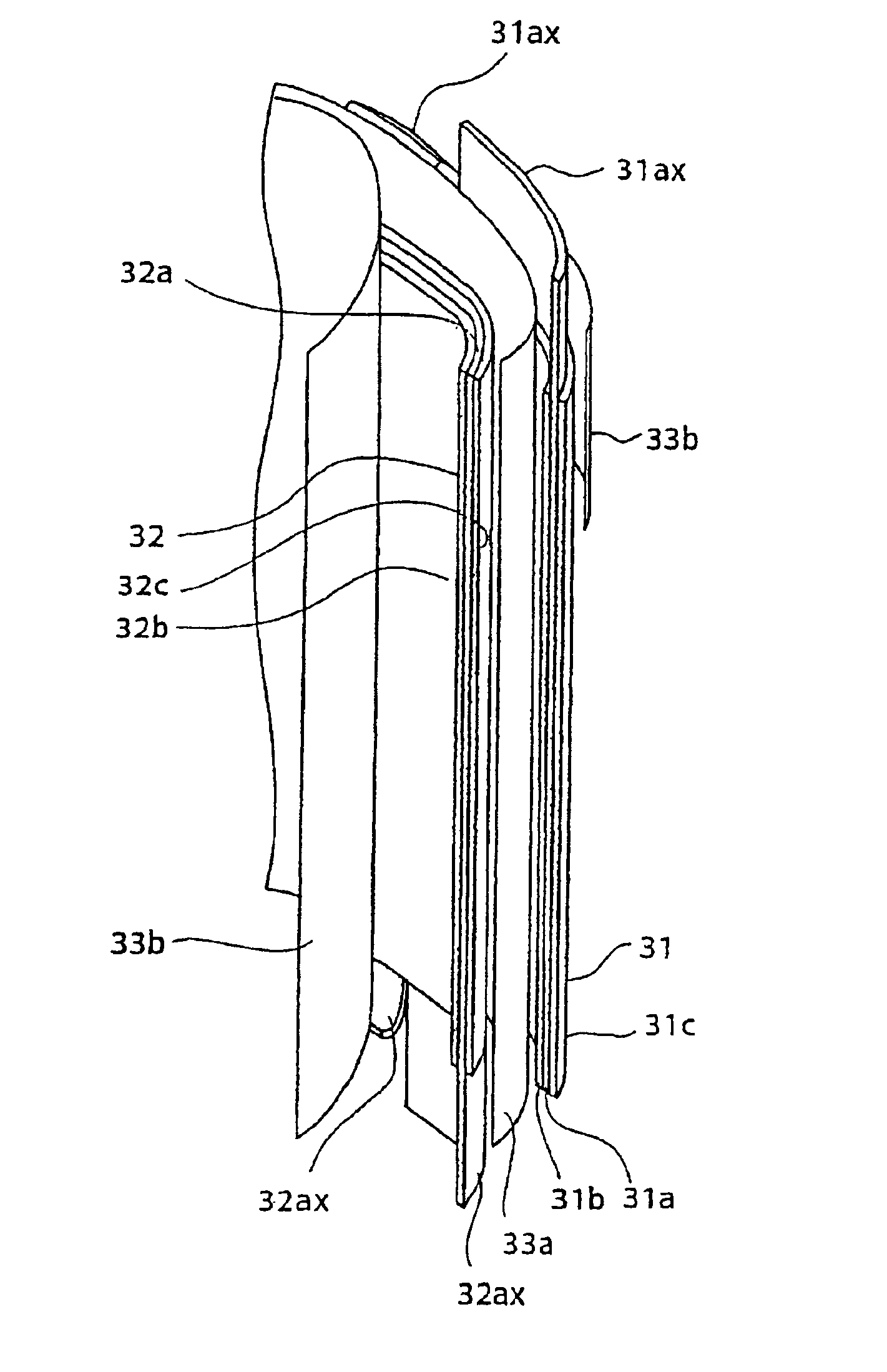
[0091]In reference of FIG. 1, in the case of Embodiment 1, preferable materials of major components, which have not been described, will be described. The collectors 31a and 32a may be a conductor having electrochemical or chemical corrosion resistance, wherein black lead, corrosion resistant metal, and so on may be used. Especially, when an non-aqueous electrolyte is used, a metallic foil such as aluminum, stainless steel, titanium steel, tantalum, and the like may be preferably used. In the present invention, it is preferable that the collectors 31a and 32a are made of a metallic foil and the thickness is about between 10 μm to 0.5 mm. Further, it is preferable that the surface is roughened because the contact between the electrode layers 31b, 31c, 32b, 32c and the collectors 31a and 32a.

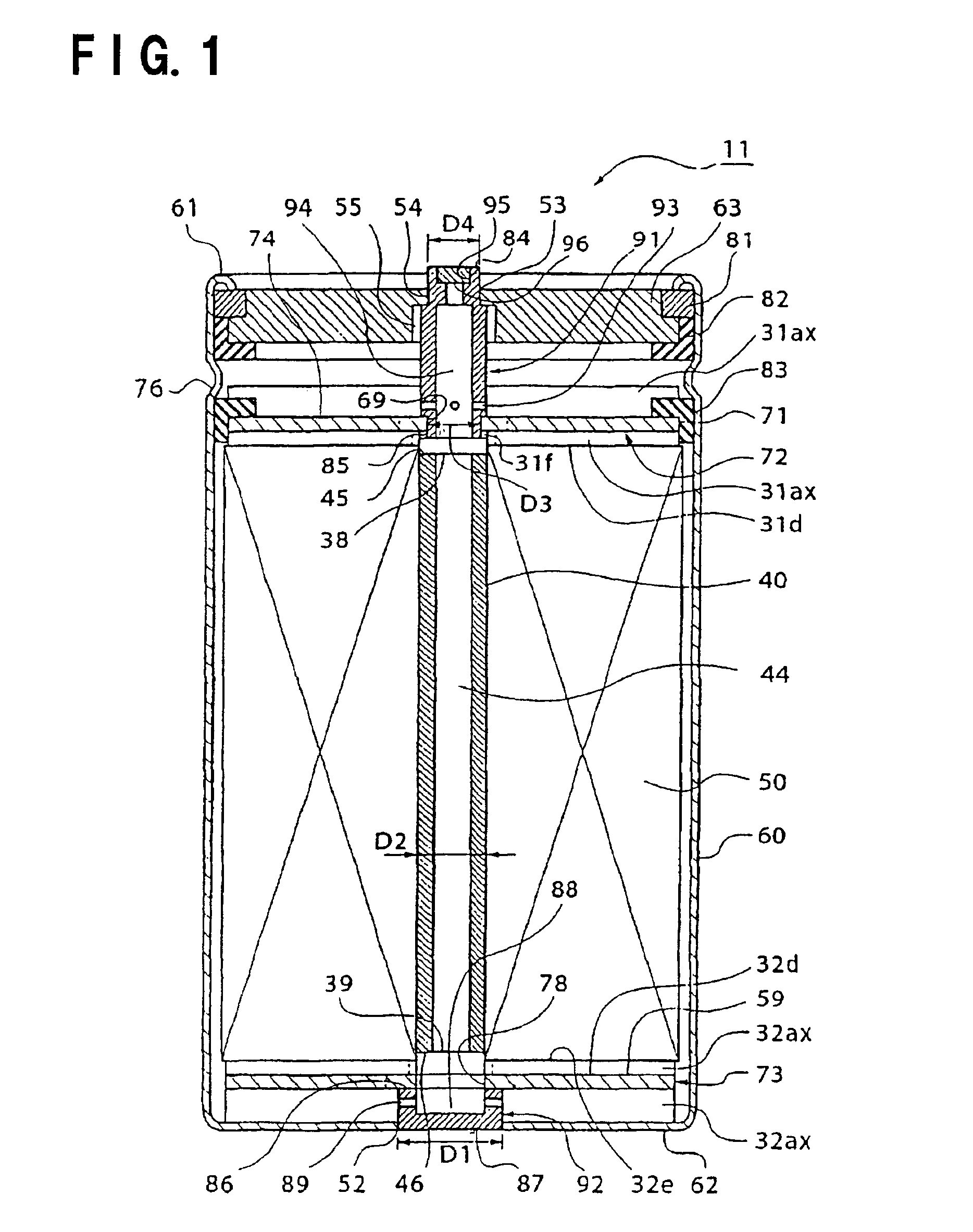
[0092]The materials of the positive collector plate 72 and the negative collector plate 73 may respectively be the materials of the positive collector 31a and the negative collector 32a, preferab...


PUM


Abstract

An electrochemical device comprises a pair of electrodes having electrode layers formed on strip-like collectors except on their strip-like portions along a longitudinal side of the strip-like collectors; strip-like separators insulating these; two collector plates connected to the strip-like portions; a case accommodating these; a lid for sealing the case; a pair of terminals connected to the collector plates and being connectable to an outside of the case. The pair of terminals is respectively connected to the lid and the case, and the pair of electrodes are wound interposing the separators therebetween, and the strip-like portions are located on both end surfaces. The electrochemical device has high volume density and low internal resistance and it can be manufactured in short time.

Description

[0001]This application is a continuation of International Application Serial No. PCT / JP00 / 06722, filed Sep. 28, 2000, and is based upon and claims the benefit of priority from the prior Japanese Patent Application No. 11-278841, filed Sep. 30, 1999, the entire contents of each of which are incorporated herein by reference.TECHNICAL FIELD[0002]The present invention relates to an electrochemical device such as an electric double layer capacitor and a secondary battery using a non-aqueous, in particular to an electrochemical device having wound electrodes.BACKGROUND ART[0003]In accordance with the recent development of electrical engineering, electronic apparatuses are miniaturized, become highly performable, and become portable. Therefore, electrochemical devices used as a power source for electronic apparatuses become more compact and less-weighted and demonstrate higher performance. Especially, chargeable secondary battery is increasingly used. The conventionally used secondary batt...

Claims


Application Information

Patent Timeline
IPC IPC(8): H01G9/00H01M6/04H01M6/10H01M2/20H01G11/22H01G4/32H01G9/10H01G11/02H01G11/24H01G11/26H01G11/28H01G11/38H01G11/42H01G11/48H01G11/54H01G11/66H01G11/70H01G11/74H01G11/78H01G11/80H01G11/82H01G11/84H01G11/86H01M10/04H01M50/179H01M50/50H01M50/528H01M50/538H01M50/627
CPCH01G4/32H01G9/10H01G9/155H01M2/06H01M2/263H01M6/10H01M10/0431Y02E60/13H01M2/36H01M2/20Y02E60/10H01M50/50H01M50/538H01G11/74H01G11/76H01G11/82H01G11/70Y02P70/50H01M50/627H01M50/179
Inventor HOZUMI, YOSHIHIROIKEDA, KATSUJIKASHIHARA, MASAMIAOKI, TOMONORIINOUE, MAKATO
Owner HONDA MOTOR CO LTD
Why Eureka
Try Eureka