
Geometry for generating a two-dimensional substantially quadrupole field

a substantially quadrupole field and geometry technology, applied in the field of quadratic fields, can solve the problems of inability to maintain trajectories and loss, and achieve the effect of increasing the average kinetic energy of ions and stable trajectories

Inactive Publication Date: 2005-05-24
THE UNIV OF BRITISH COLUMBIA
View PDF40 Cites 52 Cited by
  • Summary
  • Abstract
  • Description
  • Claims
  • Application Information

AI Technical Summary

Benefits of technology

[0022]An object of a fourth aspect of the present invention is to provide an improved method of increasing average kinetic energy of ions in a two-dimensional ion trap mass spectrometer.
[0023]In accordance with the fourth aspect of the present invention, there is provided a method of increasing average kinetic energy of ions in a two-dimensional ion trap mass spectrometer. The method comprises (a) establishing and maintaining a two-dimensional substantially quadrupole field to trap ions within a selected range of mass to charge ratios; (b) trapping ions within the selected range of mass to charge ratios; and (c) adding an excitation field to the field to increase the average kinetic energy of trapped ions within a first selected sub-range of mass to charge ratios. The first selected sub-range of mass to charge ratios is within the selected range of mass to charge ratios. The field has a quadrupole harmonic with amplitude A2, an octopole harmonic with amplitude A4, and a hexadecapole harmonic with amplitude A8. The amplitude A8 is less than the amplitude A4. The amplitude A4 is greater than 1% of A2.

Problems solved by technology

However, there is a trade off in the oscillatory trajectories that are imparted to the ions.
However, if a larger amplitude oscillation is provided, then more fragmentation will occur, but some of the ions, if the oscillation amplitude is sufficiently large, will have unstable trajectories and will be lost.

Method used


Image

  • Geometry for generating a two-dimensional substantially quadrupole field
  • Geometry for generating a two-dimensional substantially quadrupole field
  • Geometry for generating a two-dimensional substantially quadrupole field

Examples


Embodiment Construction

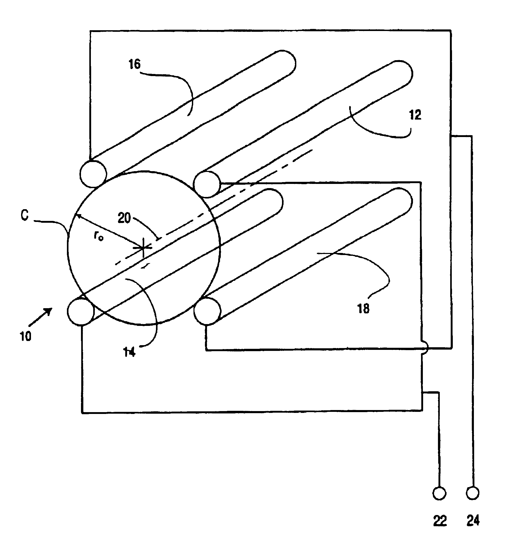
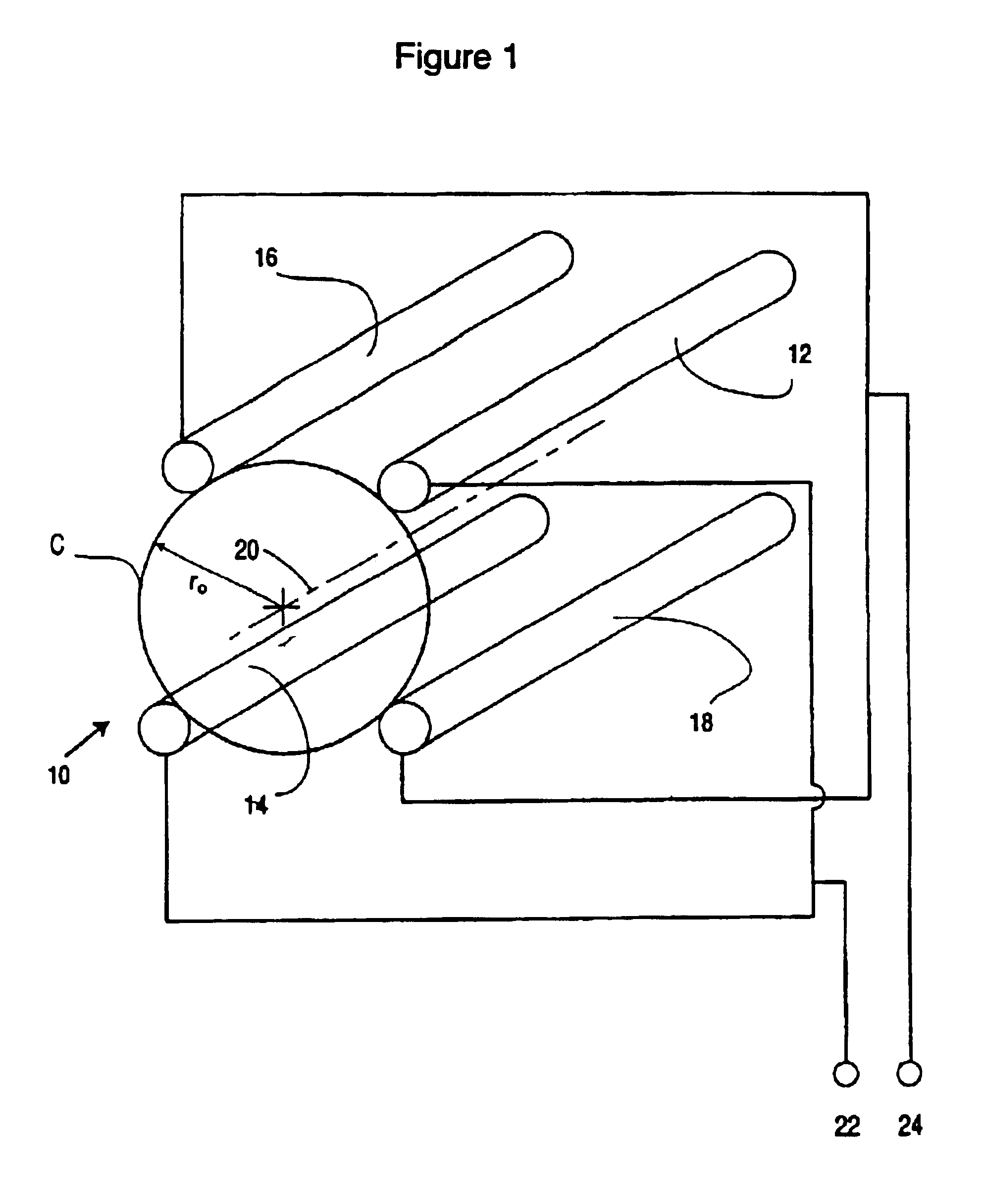
[0057]Referring to FIG. 1, there is illustrated a quadrupole rod set 10 according to the prior art. Quadrupole rod set 10 comprises rods 12, 14, 16 and 18. Rods 12, 14, 16 and 18 are arranged symmetrically around axis 20 such that the rods have an inscribed a circle C having a radius r0. The cross sections of rods 12, 14, 16 and 18 are ideally hyperbolic and of infinite extent to produce an ideal quadrupole field, although rods of circular cross-section are commonly used. As is conventional, opposite rods 12 and 14 are coupled together and brought out to a terminal 22 and opposite rods 16 and 18 are coupled together and brought out to a terminal 24. An electrical potential V(t)=+(U−V cos Ωt) is applied between terminal 22 and ground and an electrical potential V(t)=−(U−V cos Ωt) is applied between terminal 24 and ground. When operating conventionally as a mass filter, as described below, for mass resolution, the potential applied has both a DC and AC component. For operation as a ma...


PUM


Abstract

A method and apparatus for manipulating ions using a two-dimensional substantially quadrupole field, and a method of manufacturing an apparatus for manipulating ions using a two-dimensional substantially quadrupole field are described. The field has a quadrupole harmonic with amplitude A2, an octopole harmonic with amplitude A4, and higher order harmonics with amplitudes A6 and A8. The amplitude A8 is less than A4. The A4 component of the field is selected to improve the performance of the field with respect to ion selection and ion fragmentation. The selected A4 component can be added by selecting a degree of asymmetry under a 90° rotation about a central axis of the quadrupole. The degree of asymmetry is selected to be sufficient to provide the selected A4 component.

Description

FIELD OF THE INVENTION[0001]This invention relates in general to quadrupole fields, and more particularly to quadrupole electrode systems for generating an improved quadrupole field for use in mass spectrometers.BACKGROUND OF THE INVENTION[0002]The use of quadrupole electrode systems in mass spectrometers is known. For example, U.S. Pat. No. 2,939,952 (Paul et. al.) describes a quadrupole electrode system in which four rods surround and extend parallel to a central axis. Opposite rods are coupled together and brought out to one of two common terminals. Most commonly, an electric potential V(t)=+(U−V cos Ωt) is then applied between one of these terminals and ground and an electric potential V(t)=−(U−V cos Ωt) is applied between the other terminal and ground. In these formulae, U is the DC voltage, pole to ground, and V is the zero to peak radio frequency (RF) voltage, pole to ground.[0003]In constructing a linear quadrupole, the field may be distorted so that it is not an ideal quadr...

Claims


Application Information

Patent Timeline
IPC IPC(8): H01J49/34H01J49/42G01N27/62H01J49/06
CPCH01J49/4225H01J49/4215
Inventor SOUDAKOV, MIKHAILDOUGLAS, DONALD J.DING, CHUAN-FAN
Owner THE UNIV OF BRITISH COLUMBIA
Learn More