
Apparatus and method for monitoring and tuning an ion beam in ion implantation apparatus

a technology of ion beam and ion implantation, which is applied in the field of ion beam monitoring and tuning, can solve the problems of not being able to adjust mechanically, and achieve the effect of quick adjustment of the angle of deflection of the ion beam

Inactive Publication Date: 2005-05-24
APPLIED MATERIALS INC
View PDF12 Cites 14 Cited by
  • Summary
  • Abstract
  • Description
  • Claims
  • Application Information

AI Technical Summary

Benefits of technology

[0019]It is quicker to adjust the angle of deflection of the ion beam electrostatically than mechanically. There is less scope for accidentally misaligning the ion source relative to the beam line if it is not necessary to touch the extraction electrodes during set up. Furthermore, electrostatic deflection allows the ion beam angle to be adjusted during doping, which clearly could not be done with mechanical adjustment.

Problems solved by technology

Furthermore, electrostatic deflection allows the ion beam angle to be adjusted during doping, which clearly could not be done with mechanical adjustment.

Method used


Image

  • Apparatus and method for monitoring and tuning an ion beam in ion implantation apparatus
  • Apparatus and method for monitoring and tuning an ion beam in ion implantation apparatus
  • Apparatus and method for monitoring and tuning an ion beam in ion implantation apparatus

Examples


Embodiment Construction

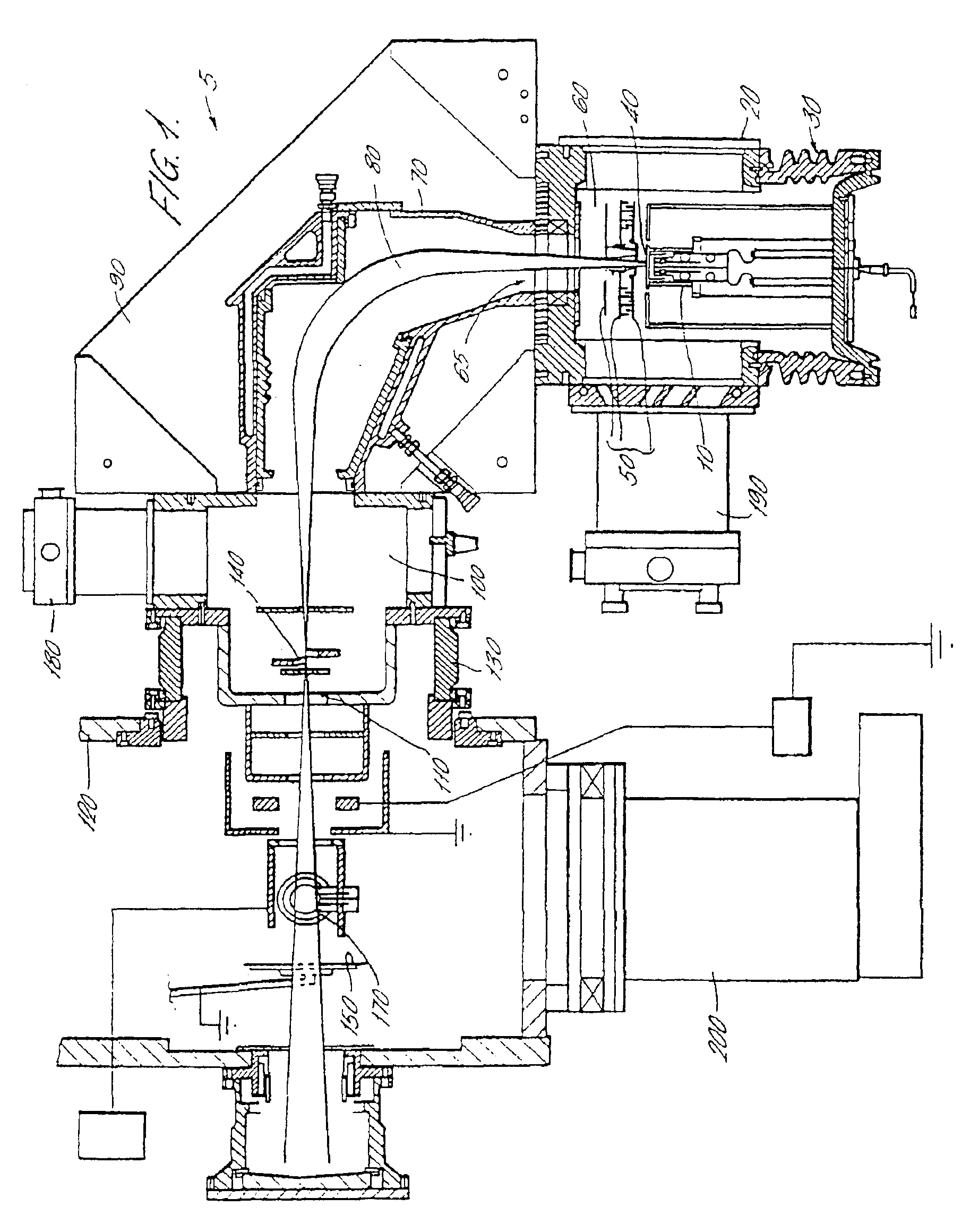
[0039]Referring to FIG. 1, a schematic sectional view of an ion implanter 5 is shown. The implanter includes an ion source 10, such as a Freeman or Bernas source. The ion source 10 is fed with a supply of atoms of, or molecules containing, the element, ions of which are to be implanted in a target substrate 150. The molecules may be supplied to the ion source 10 in gaseous or vapour form. As will be well known to those skilled in the art, the ion source strips electrons from the atoms or molecules to generate a plasma.

[0040]The ion source 10 is mounted within an evacuated ion source housing 20, but is spaced and insulated therefrom by first insulating bushing 30.

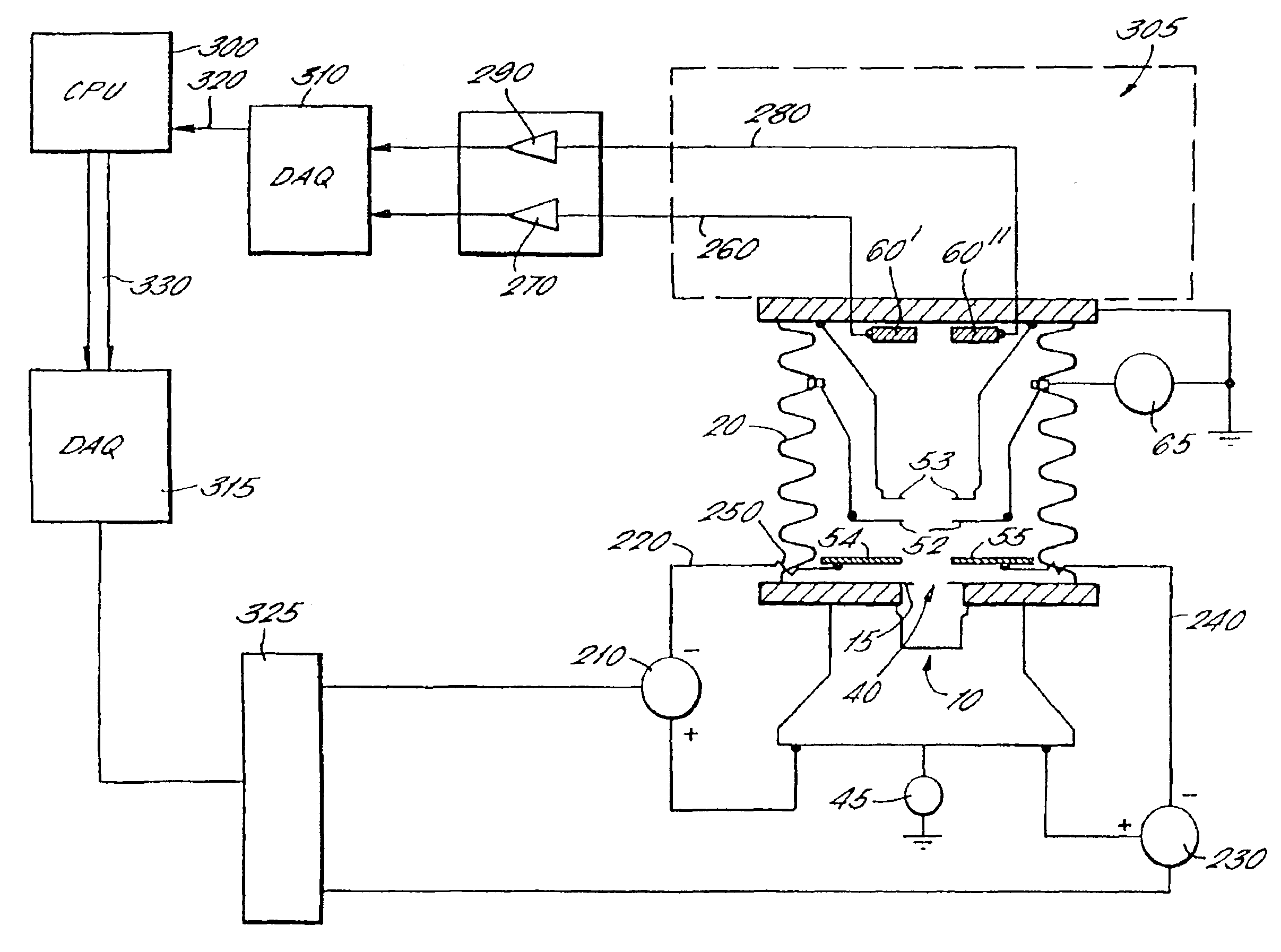
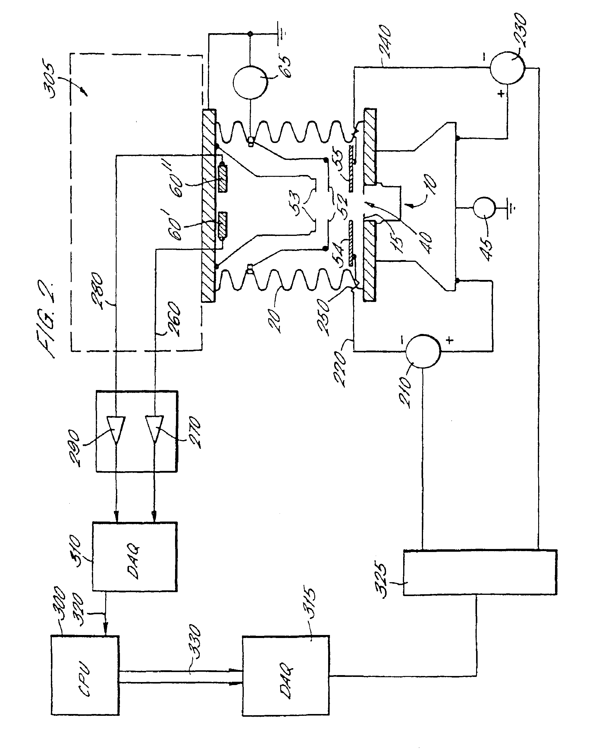
[0041]Ions from the plasma exit the ion source 10 through an ion source slit 40 in the front face thereof. Located immediately adjacent the ion source slit 40 is a set of extraction electrodes 50 which will be described in more detail with reference to FIG. 2 below. In general, however, the extraction electrodes 50 are adjus...


PUM

PropertyMeasurementUnit
energyaaaaaaaaaa
voltageaaaaaaaaaa
voltageaaaaaaaaaa

Abstract

An ion implanter has an ion source (10) and an ion beam extraction assembly (50) for extracting the ions. The extraction assembly (50) is a tetrode structure and one of the pairs of extraction electrodes (51) has left and right ports (54, 55) located in opposite sides of the ion beam emerging from the ion source (10). The left and right electrode ports (54, 55) are electrically isolated from each other and connected to independent voltage sources (210, 230). The ion implanter also has a baffle plate (60) at the entrance to a mass analyser (90) downstream of the extraction assembly (50). The baffle plate (60) is also split into two halves (60′ and 60″). By measuring the beam current incident on the two halves (60′, 60″) of the baffle (60), the relative voltages supplied to the left and right electrode parts (54, 55) may be adjusted so as to steer the ion beam and adjust the angle of incidence of the longitudinal axis thereof relative to the input of the analysing magnet (90).

Description

[0001]This application claims priority under 35 U.S.C. § 119 of United Kingdom Application No. 9900145.5, which has a filing date of Jan. 5, 1999, in accordance with 37 C.F.R. § 1.55(1)(ii) and which was identified in accordance with the regulations under the Patent Cooperation Treaty as a priority document to PCT International Application No. PCT / GB99 / 04402 from which this application is derived.FIELD OF THE INVENTION[0002]The present invention relates to ion beam monitoring and tuning in, for example, an ion implantation apparatus for implanting ions from an ion beam into target substrates such as semiconductor wafers.BACKGROUND OF THE INVENTION[0003]In the manufacture of semiconductor devices and integrated circuits it is known to modify the semiconductor substrate material by diffusing or implanting atoms or molecules of selected dopants into the substrate. The substrate materials are usually silicon or germanium.[0004]This process produces regions of selected varying conductivi...

Claims


Application Information

Patent Timeline
Patent Type & Authority Patents(United States)
IPC IPC(8): H01J37/30H01J37/304H01J37/147H01J37/317C23C14/48H01J37/04H01L21/265
CPCH01J37/1471H01J37/3171H01J37/304H01J2237/1501
Inventor HOLMES, ANDREW JAMES TIMOTHYBURGIN, DAVID RICHARDPOVALL, SIMONARMOUR, DAVID GEORGEARNOLD, DREW
Owner APPLIED MATERIALS INC
Learn More