Electroluminescent devices

Inactive Publication Date: 2005-05-24
CAMBRIDGE DISPLAY TECH LTD
View PDF32 Cites 63 Cited by
  • Summary
  • Abstract
  • Description
  • Claims
  • Application Information

AI Technical Summary

Benefits of technology

[0033]Preferably both the components of the emissive layer are soluble, and most preferably both are soluble in the sam

Problems solved by technology

However, there are several significant problems.
This makes it difficult to inject holes into the emissive layer, i.e. high electric fields are required in order to encourage holes to inject into the semiconductor layer.
One solution to this problem would be to choose another material for the anode, but it is difficult to find a preferable al

Method used


Image

  • Electroluminescent devices
  • Electroluminescent devices
  • Electroluminescent devices

Examples


Embodiment Construction

[0077]Table 1 gives material properties of some light-emissive materials:

[0078]

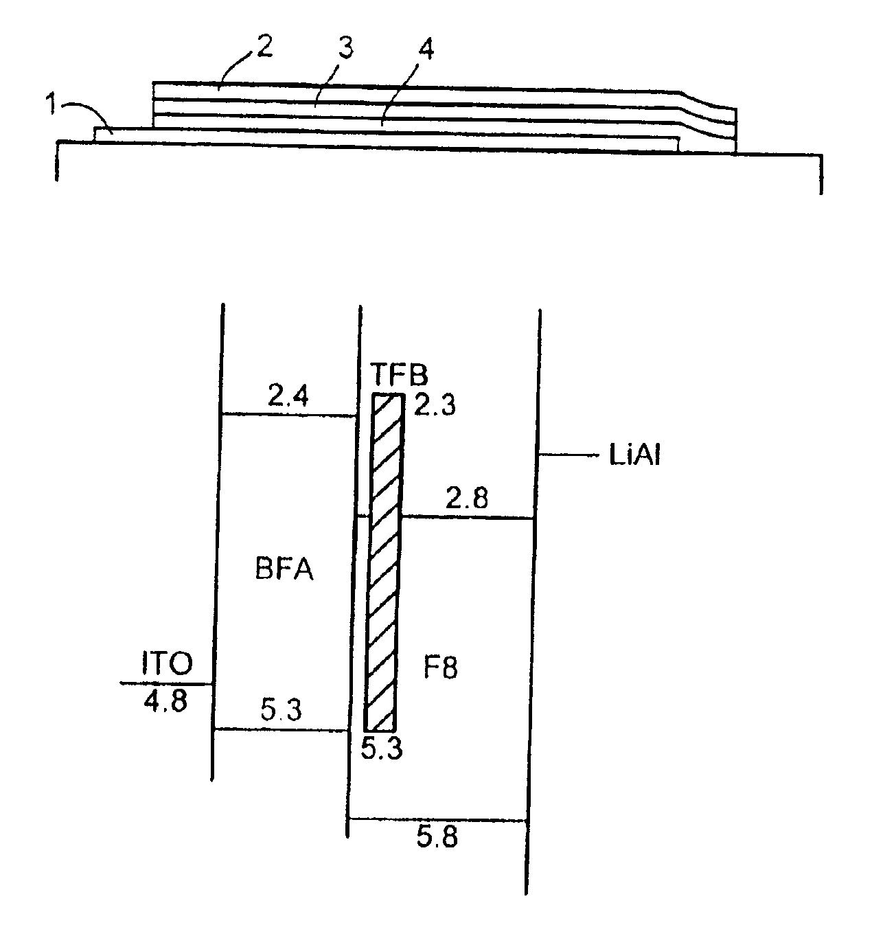
TABLE 1% PL% PLHOMO LUMOOpticalEffi-Effi-LevelLevelgapEmissionMaterialciency1ciency2(eV)(eV)(eV)Colour F8 80 50 5.8 2.8 3.0 BlueTFB40155.32.33.0BluePFMO40135.02.03.0BluePFM2055.02.12.9Blue5F8BT95805.93.52.4GreenBis-DMOS5.73.52.2GreenPPVPPVA35.63.22.6GreenNotes to table 1: 1Photoluminescence (PL) efficiencies measured using the technique of Halls et al. (see above). 2Measured using a refined technique based on that of Halls et al. 3See discussion of FIG. 25 below.

[0079]The HOMO positions were estimated from electrochemical measurement. The optical gaps were determined from the UV / visible absorbance spectrum. The LUMO positions were estimated from the HOMO position and the optical gap. 5F8BT is an abbreviation for a blend of 5% F8BT with 95% F8 w / w.

[0080]Of the blue emitters, F8 has the highest PL efficiency of these materials. Therefore, of these materials it would normally be the material of...


PUM

PropertyMeasurementUnit
Energyaaaaaaaaaa
Energyaaaaaaaaaa
Energyaaaaaaaaaa

Abstract

An electroluminescent device comprising: a first charge carrier injecting layer for injecting positive charge carriers; a second charge carrier injecting layer for injecting negative charge carriers; and a light-emissive layer located between the charge carrier injecting layers and comprising a mixture of: a first component for accepting positive charge carriers from the first charge carrier injecting layer; a second component for accepting negative charge carriers from the second charge carrier injecting layer; and a third, organic light-emissive component for generating light as a result of combination of charge carriers from the first and second components; at least one of the first, second and third components forming a type II semiconductor interface with another of the first, second and third components.

Description

FIELD OF THE INVENTION[0001]This invention relates to electroluminescent devices, especially those that employ an organic material for light emission.BACKGROUND OF THE INVENTION[0002]Electroluminescent devices that employ an organic material for light emission are described in PCT / WO90 / 13148 and U.S. Pat. No. 4,539,507, the contents of both of which are incorporated herein by reference. The basic structure of these devices is a light-emissive organic layer, for instance a film of a poly(p-phenylenevinylene (“PPV”), sandwiched between two electrodes. One of the electrodes (the cathode) injects negative charge carriers (electrons) and the other electrode (the anode) injects positive charge carriers (holes). The electrons and holes combine in the organic layer generating photons. In PCT / WO90 / 13148 the organic light-emissive material is a polymer. In U.S. Pat. No. 4,539,507 the organic light-emissive material is of the class known as small molecule materials, such as (8-hydroxyquinolino...

Claims


Application Information

Patent Timeline
IPC IPC(8): H01L51/50C09K11/06H05B33/10H05B33/14
CPCH01L51/0039H01L51/5024H01L51/0003C08G2261/3142C08G2261/3162C08G2261/3246H01L2251/5384H01L51/5056H01L51/5072H01L51/0043H10K71/12H10K85/115H10K85/151H10K50/11H10K2101/40H10K50/12H10K50/15H10K50/16H10K2101/90H10K50/17
Inventor BURROUGHES, JEREMY HENLEYFRIEND, RICHARD HENRYBRIGHT, CHRISTOPHER JOHNLACEY, DAVID JOHNDEVINE, PETER
Owner CAMBRIDGE DISPLAY TECH LTD
Why Eureka
Try Eureka