Electronic apparatus with two quartz crystal oscillators utilizing different vibration modes

a quartz crystal oscillator and vibration mode technology, applied in the field of electronic equipment, can solve the problems of inability to obtain an electronic apparatus comprising a smaller quartz crystal oscillator, inability to provide electronic, and fundamental mode vibration of the resonator jumps to a second overtone, etc., to achieve small series resistance, high quality factor, and high frequency stability

Inactive Publication Date: 2005-05-24
PIEDEK TECHN LAB
View PDF9 Cites 19 Cited by
  • Summary
  • Abstract
  • Description
  • Claims
  • Application Information

AI Technical Summary

Benefits of technology

[0017]It is an another object of the present invention to provide an electronic apparatus comprising a quartz crystal oscillator comprising a quartz crystal oscillating circuit with a miniature quartz crystal tuning fork resonator, capable of vibrating in a flexural mode, and having a high frequency stability, a small series resistance R1 and a high quality factor Q1, whose frequency for a fundamental

Problems solved by technology

Heretofore, however, it has been impossible to obtain an electronic apparatus comprising a smaller quartz crystal oscillator with a conventional miniaturized quartz crystal tuning fork resonator, capable of vibrating in a flexural mode, and having a high frequency stability, a small series resistance and a high quality factor.
Additionally, for example, there has been a big problem in the conventional quartz crystal oscillator with the conventional quartz crystal tuning fork resonator, such that a fundamental mode vibration of the resonator jumps to a second

Method used


Image

  • Electronic apparatus with two quartz crystal oscillators utilizing different vibration modes
  • Electronic apparatus with two quartz crystal oscillators utilizing different vibration modes
  • Electronic apparatus with two quartz crystal oscillators utilizing different vibration modes

Examples


first embodiment

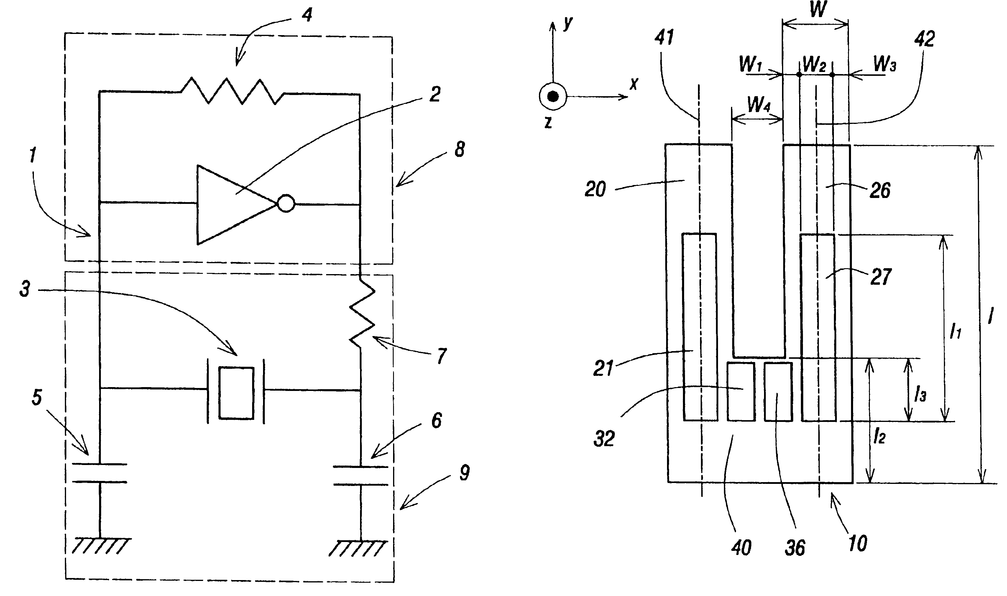
[0053]FIG. 4 shows a general view of a flexural mode, quartz crystal tuning fork resonator 10 constructing a quartz crystal oscillator, which constructs an electronic apparatus of the present invention and its coordinate system o-xyz. A cut angle θ, which has a typical value of 0° to 10°, is rotated from a Z-plate perpendicular to the z axis about the x axis. The quartz crystal resonator 10 comprises two tuning fork tines 20 and 26 and a tuning fork base 40. The tines 20 and 26 have grooves 21 and 27 respectively, with the grooves 21 and 27 extending into the base 40. In addition, the base 40 has the additional grooves 32 and 36.

[0054]FIG. 5 shows a cross-sectional view of the tuning fork base 40 for quartz crystal resonator 10 along line 5—5 of FIG. 4. In FIG. 5, the shape of the electrode construction within the base 40 for the quartz crystal resonator of FIG. 4 is described in detail. The section of the base 40 which couples to the tine 20 has the grooves 21 and 22 cut into the o...

second embodiment

[0074]FIG. 7a and FIG. 7b are a top view and a side view for a width-extensional mode quartz crystal resonator constructing a quartz crystal oscillator, which constructs an electronic apparatus of the present invention. The resonator 62 comprises vibrational portion 63, connecting portions 66, 69 and supporting portions 67, 80 including respective mounting portions 68, 81. In addition, the supporting portions 67 and 80 have respective holes 67a and 80a. Also, electrodes 64 and 65 are disposed opposite each other on upper and lower faces of the vibrational portion 63, the electrodes have opposite electrical polarities. Namely, a pair of electrodes is disposed on the vibrational portion. In this case, a fundamental mode vibration can be excited easily.

[0075]In addition, the electrode 64 extends to the mounting portion 81 through the one connecting portion 69 and the electrode 65 extends to the mounting portion 68 through the other connecting portion 66. In this embodiment, the electro...

fourth embodiment

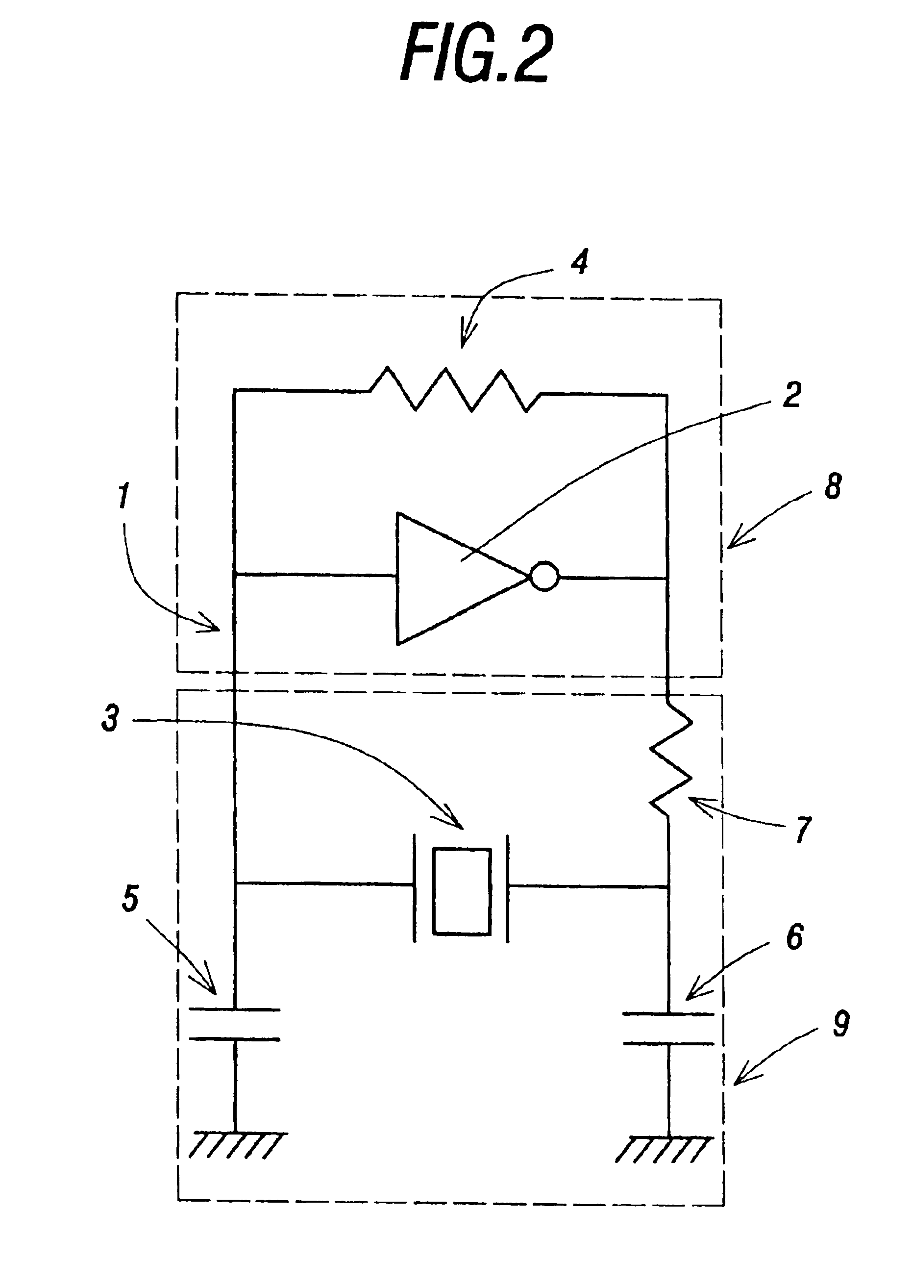
[0087]FIG. 9 shows a cross-sectional view of a quartz crystal oscillator, which constructs an electronic apparatus of the present invention. The quartz crystal oscillator 190 comprises a quartz crystal oscillating circuit, a case 91 and a lid 92. In this embodiment, circuit elements constructing the oscillating circuit are housed in a quartz crystal unit comprising a flexural mode, quartz crystal tuning fork resonator 90, the case 91 and the lid 92. Also, the quartz crystal oscillating circuit of this embodiment comprises an amplifier 98 including a feedback resistor, the quartz crystal tuning fork resonator 90, capacitors (not shown here) and a drain resistor (not shown here), and a CMOS inverter is used as the amplifier 98.

[0088]In addition, in this embodiment, the resonator 90 is mounted at a mounting portion 94 of the case 91 by conductive adhesives 96 or solder As described above, the amplifier 98 is housed in the quartz crystal unit and mounted at the case 91. Also, the case 9...


PUM


Abstract

An electronic apparatus has a display portion and quartz crystal oscillators having different modes of vibration. Each of the quartz crystal oscillators has a quartz crystal oscillating circuit having a quartz crystal resonator. The quartz crystal resonator of one of the quartz crystal oscillating circuits is a width-extensional mode quartz crystal resonator capable of vibrating in a width-extensional mode. The width-extensional mode quartz crystal resonator has a vibrational portion, connecting portions disposed at ends of the vibrational portion, supporting portions connected to the vibrational portion through the connecting portions, and electrodes disposed on upper and lower surfaces of the vibrational portion. The quartz crystal oscillating circuit having the width-extensional mode quartz crystal resonator outputs a clock signal for operating the electronic apparatus to display time information at the display portion.

Description

BACKGROUND OF THE INVENTION[0001]1. Field of the Invention[0002]The present invention relates to an electronic apparatus comprising at least a display portion and a quartz crystal oscillator.[0003]2. Background Information[0004]There are many electronic apparatuses comprising at least a display portion and a quartz crystal oscillator. For example, cellular phones, wristwatches and pagers comprising a quartz crystal oscillator are well known. Recently, because of high stability for frequency, miniaturization and the light weight nature of these electronic apparatus, the need for an electronic apparatus comprising a smaller quartz crystal oscillator with a high frequency stability has arisen. For example, the quartz crystal oscillator with a quartz crystal tuning fork resonator, which is capable of vibrating in a flexural mode, is widely used as a time standard in an electronic apparatus such as cellular phones, wristwatches and pagers. Similar to this, the same need has also arisen f...

Claims


Application Information

Patent Timeline
IPC IPC(8): H03H9/00H03H9/215H03H9/10H03H9/05H03H9/21
CPCH03H9/0547H03H9/1021H03H9/215H03H2003/0492H03H2003/026
Inventor KAWASHIMA, HIROFUMI
Owner PIEDEK TECHN LAB
Why Eureka
Try Eureka