
Frequency comb analysis

a frequency comb and analysis technology, applied in the field of frequency comb analysis, can solve the problems of large transmission distance, limited application of optical frequency pulsing, and overlap of pulses over large transmission distances, and achieve the effect of increasing the specificity of detection

Inactive Publication Date: 2005-05-24
EXCEL MEDICAL VENTURES
View PDF7 Cites 45 Cited by
  • Summary
  • Abstract
  • Description
  • Claims
  • Application Information

AI Technical Summary

Benefits of technology

[0009]In one embodiment, at least one monochromatic component or spectral line of the frequency comb, once generated, is focused by, for example a lens, onto a substrate for identification and / or analysis. The frequency comb may be focused to a single point for detection of a discrete molecular entity. For example, in a preferred embodiment, frequency combs are used to determine the identity of individual nucleic acids in a linearized strand of deoxyribonucleic acid (DNA). The use of frequency combs enables detection of the sequence of DNA where detection with single-source light would not be possible. Each monochromatic component of the frequency comb comprises photons having energy E that is proportional to frequency, represented by E=hν. A substance to be analyzed, such as a nucleic acid, absorbs a photon of a specific frequency corresponding to an energy transition in the nucleic acid. Observation of absorption of photons of the specific frequency provides information about the identity of the nucleic acid in question. Pulses of extremely short duration, such as pulses in the range of 1 picosecond to less than 10 femtoseconds, interact with the substance in time periods so short that the substance has insufficient time to undergo chemical reaction or even to vibrate. Accordingly, frequency combs of the invention allow a selection of frequency components best suited to identify the target sample. In fact, the number of emission lines produced by the average frequency comb, along with the ability to rapidly pulse a sample, allows redundant probing of the sample to increase the specificity of detection. A frequency spacing of approximately 10 GHz between monochromatic components of a frequency comb generated with a laser having a wavelength of approximately 800 nm has monochromatic components that differ in wavelength by dimensions of the order of 0.1 Angstroms.

Problems solved by technology

Each of these uses of optical frequency pulsing has limitations that have prevented full exploitation of the technology.
For example, a limitation in the use of optical frequency pulsing for transmission of information is the relatively wide bandwidth of individual frequency pulses, resulting in overlapping pulses over large transmission distances.
Over fairly modest distances, the overlap of frequency lines can result in a loss of digital information content.
Another limitation is the difficulty in generating a plurality of different, closely spaced frequencies which limits signal resolution.
The identification and characterization of physical substrates using frequency pulses is limited by the ability to provide sufficiently narrow, stable pulses at high frequency in order to obtain precise physical chemical resolution of the target substrate.
Such measurements necessarily result in decreased resolution in space and time.
Therefore, interferometric measurements are less than ideal.

Method used


Image

  • Frequency comb analysis
  • Frequency comb analysis
  • Frequency comb analysis

Examples


example 1

Generation of a Frequency Comb

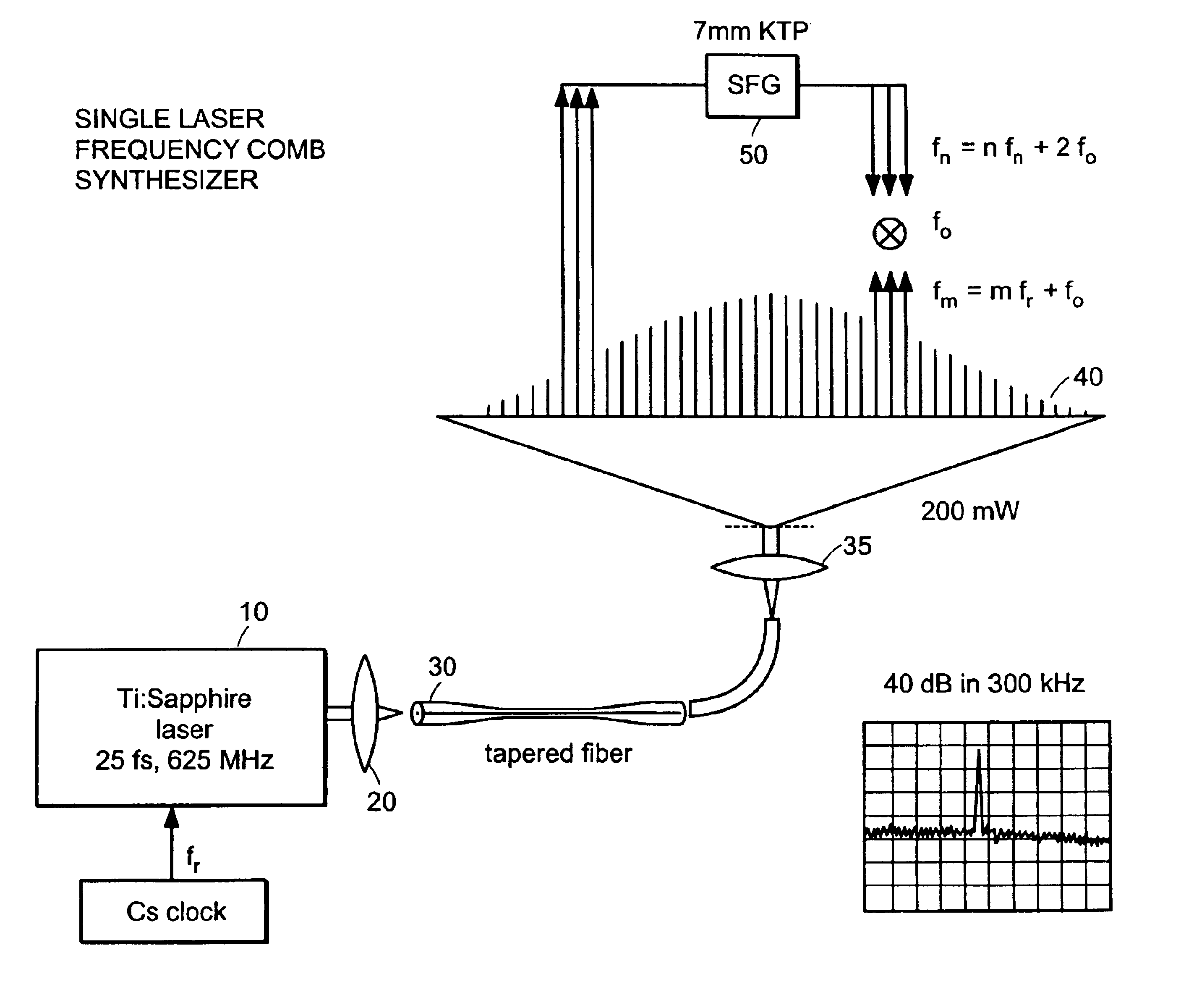
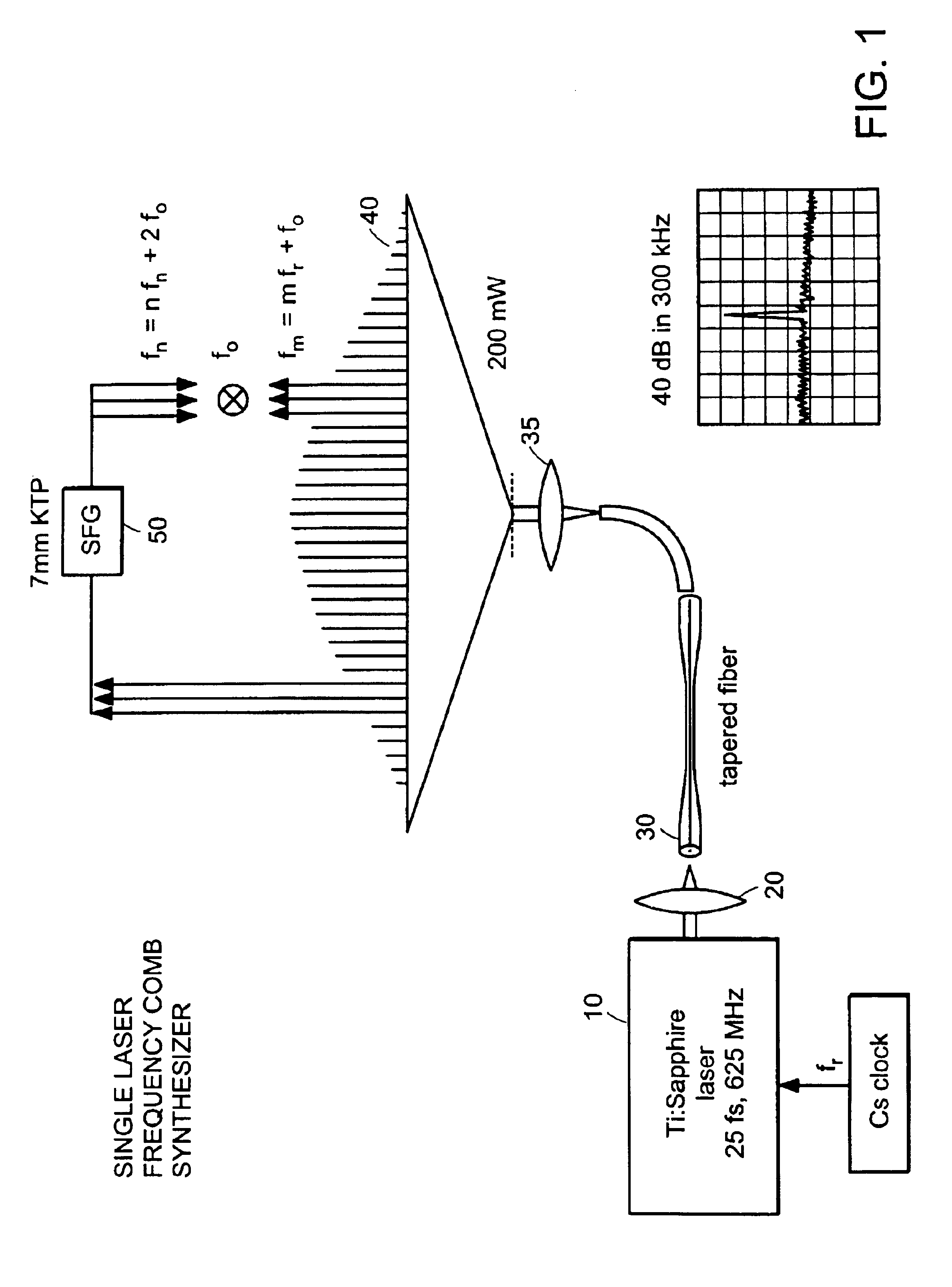
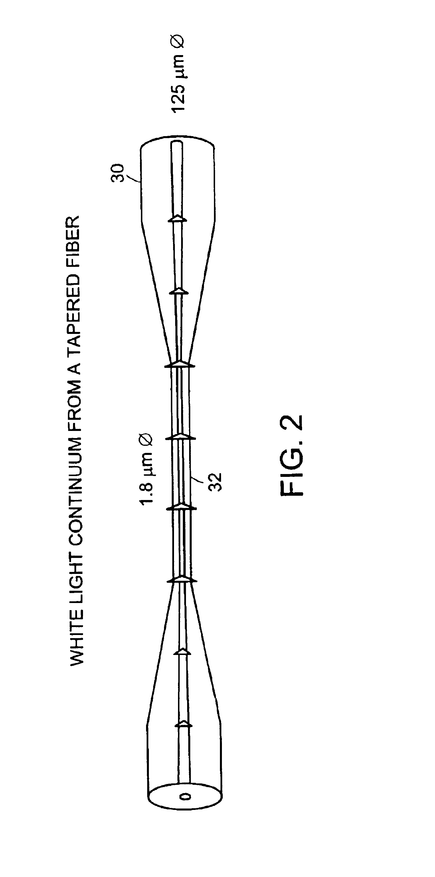
[0042]Referring to FIG. 1, a source 10, such as a Titanium (Ti): sapphire (Al2O3:Ti3+) laser, operated in pulsed mode, for example at a frequency of 625 MHz, with a pulse duration of 25femtoseconds (fs), provides illumination that is focused by a lens 20 into an optical path. The optical path can be an optical fiber 30, such as the tapered optical fiber shown in greater detail in FIG. 2, that has a constriction 32. In one embodiment, the tapered optical fiber 30 has an overall diameter of about 125 micrometers and a constriction 32 (or “waist”) having a diameter that is 1.8 micrometers in diameter. In some embodiments, the waist 32 is 1.5 micrometers in diameter. The interaction of the pulsed illumination with the constriction 32 creates a frequency comb 40 (“frequency comb illumination”). The frequency comb illumination exiting the tapered optical fiber 30 is focussed by a lens 35. In one embodiment, the frequency comb illumination contains optical rad...

example 2

Use of a Frequency Comb in Biologically Important Applications

[0046]As shown schematically in FIG. 3A, the frequency comb illumination may be focused onto substantially a point of light 65 that coincides with a point within a channel 60 through which a fluid 70 can flow, as indicated by the arrow 70. The channel is fabricated from a suitably transparent material. The channel 60 carries a fluid 70 comprising a chemical substance to be identified or that is intended to otherwise react with at least a portion of the frequency comb illumination. For example, a solution containing DNA may move down the channel 60 into the illuminated area. As will be discussed in more detail below, the DNA can be caused to move under the action of electric fields, or alternatively the DNA can be carried by a moving carrier fluid. As the frequency comb illumination passes through the channel 60, one or more frequency components of the frequency comb interact preferentially with the chemical substance, suc...

example 3

Use of a Frequency Comb in Optical Communication Applications

[0058]In the field of telecommunication, an exemplary frequency comb having a spacing of approximately 50 MHz and a one octave spectral bandwidth from approximately 600 nm to approximately 1200 m, which is equivalent to a bandwidth extending from 500×1012 per second or 500 TeraHertz (THz) to 250 THz, (i.e., 250 THz bandwidth), there would be approximately 5×10⁶ or 5 million discrete monochromatic components in the frequency comb. At a frequency separation of 100 MHz, which is a common separation between adjacent channels in present-day telecommunication, the frequency comb would support approximately 2.5 million separate channels. A discussion of some of the features of optical communications appears in U.S. Pat. No. 5,631,758, the entire disclosure of which is incorporated herein by reference. Because the repetition rate can be controlled, as described above, the frequency spacing in the frequency comb can be controlled. ...


PUM

PropertyMeasurementUnit
frequencyaaaaaaaaaa
frequencyaaaaaaaaaa
diameteraaaaaaaaaa

Abstract

Methods and apparatus for generating a frequency comb and for its use in analyzing materials and in telecommunications. The frequency comb is generated by passing pulsed light from a laser through an optical fiber having a constriction. The frequency comb comprises a plurality of monochromatic components separated in frequency by a substantially constant frequency increment. The monochromatic components are used to probe materials for analysis. In preferred embodiments, the materials are DNA, RNA, PNA and other biologically important molecules and polymers. Optical responses are observed and used to analyze or identify samples. In telecommunication applications, the individual monochromatic components serve as carriers for individual communication channels that can carry information of any of a variety of types, such as voice, data and images.

Description

CROSS-REFERENCE TO RELATED APPLICATIONS[0001]This application claims the benefit of U.S. provisional application Ser. No. 60 / 283,773, filed Apr. 13, 2001, which application is incorporated by reference herein.FIELD OF THE INVENTION[0002]The invention relates to methods and materials for analyzing and characterizing samples and for improving optical communications.BACKGROUND OF THE INVENTION[0003]Optical frequency pulsing has a host of diverse uses. However, there are two principal categories into which optical frequency pulsing may conveniently be placed. A first has to do with using frequency pulsing to encode information for transmission across fiber optic lines. A second broad category of use for optical frequency pulsing is the identification of physical properties of molecules. Each of these uses of optical frequency pulsing has limitations that have prevented full exploitation of the technology.[0004]For example, a limitation in the use of optical frequency pulsing for transmi...

Claims


Application Information

Patent Timeline
Patent Type & Authority Patents(United States)
IPC IPC(8): G01N21/31H04B10/155H04B10/152
CPCG01N21/255H04B10/506H04B10/503G01N21/31G01J3/10
Inventor HAENSCH, THEODOR W.MEI, MICHAELHOLZWARTH, RONALDBLUME, FREDRICK R.
Owner EXCEL MEDICAL VENTURES
Learn More