
Positioning control device for two-stage actuator

a technology of positioning control and actuator, which is applied in the direction of recording information storage, maintaining head carrier alignment, instruments, etc., can solve the problems of limiting the frequency band affecting the operation of fine-moving actuators alone, and affecting the accuracy of the positioning control system, etc., to achieve high speed and high accuracy

Inactive Publication Date: 2005-05-24
HITACHI GLOBAL STORAGE TECH JAPAN LTD +1
View PDF2 Cites 23 Cited by
  • Summary
  • Abstract
  • Description
  • Claims
  • Application Information

AI Technical Summary

Benefits of technology

[0009]It is therefore the primary object of the present invention to realize a positioning control device including adaptive identification means capable of estimating the input-output characteristics of the fine-movement actuator at high speed and with high accuracy.
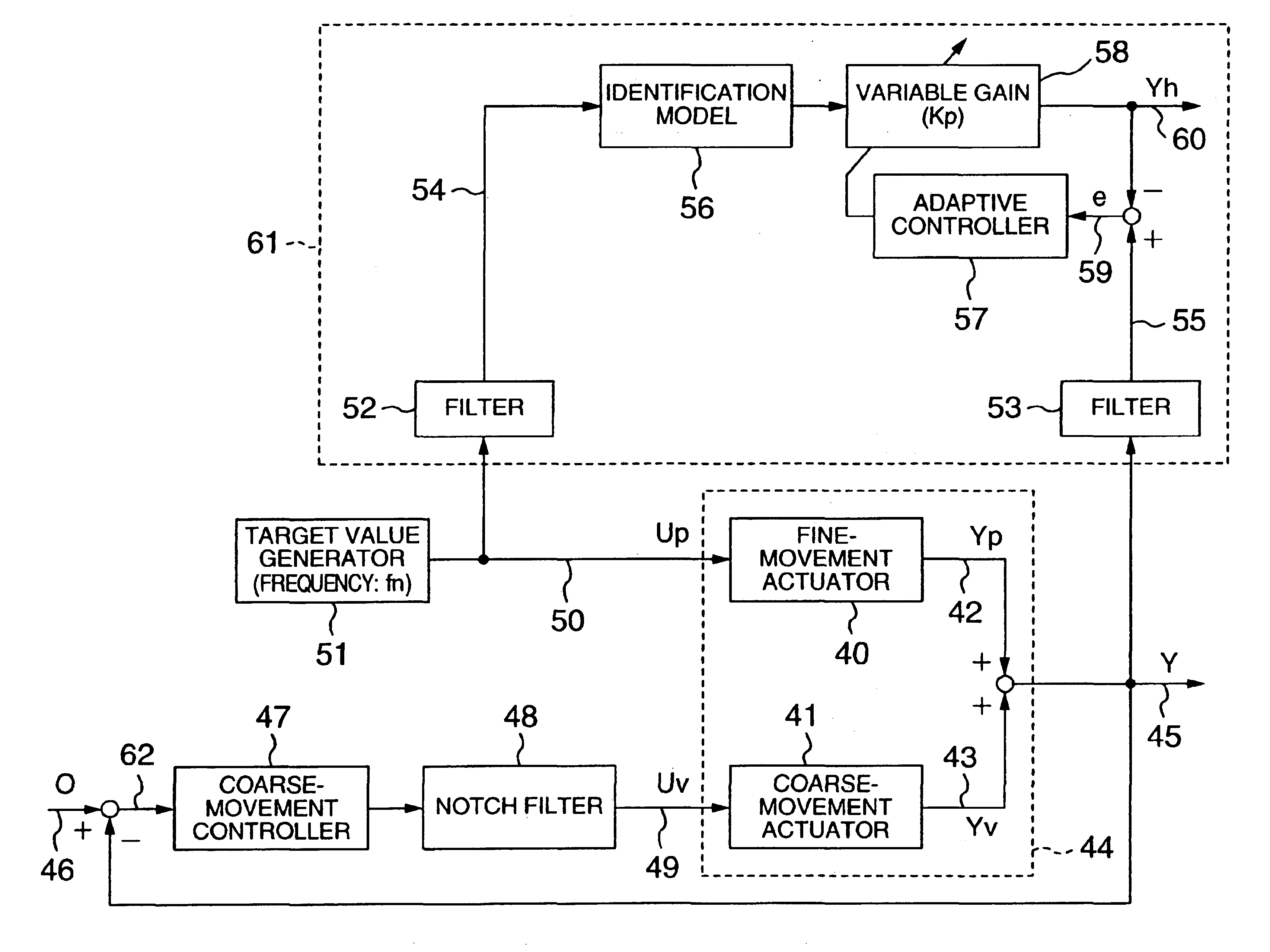
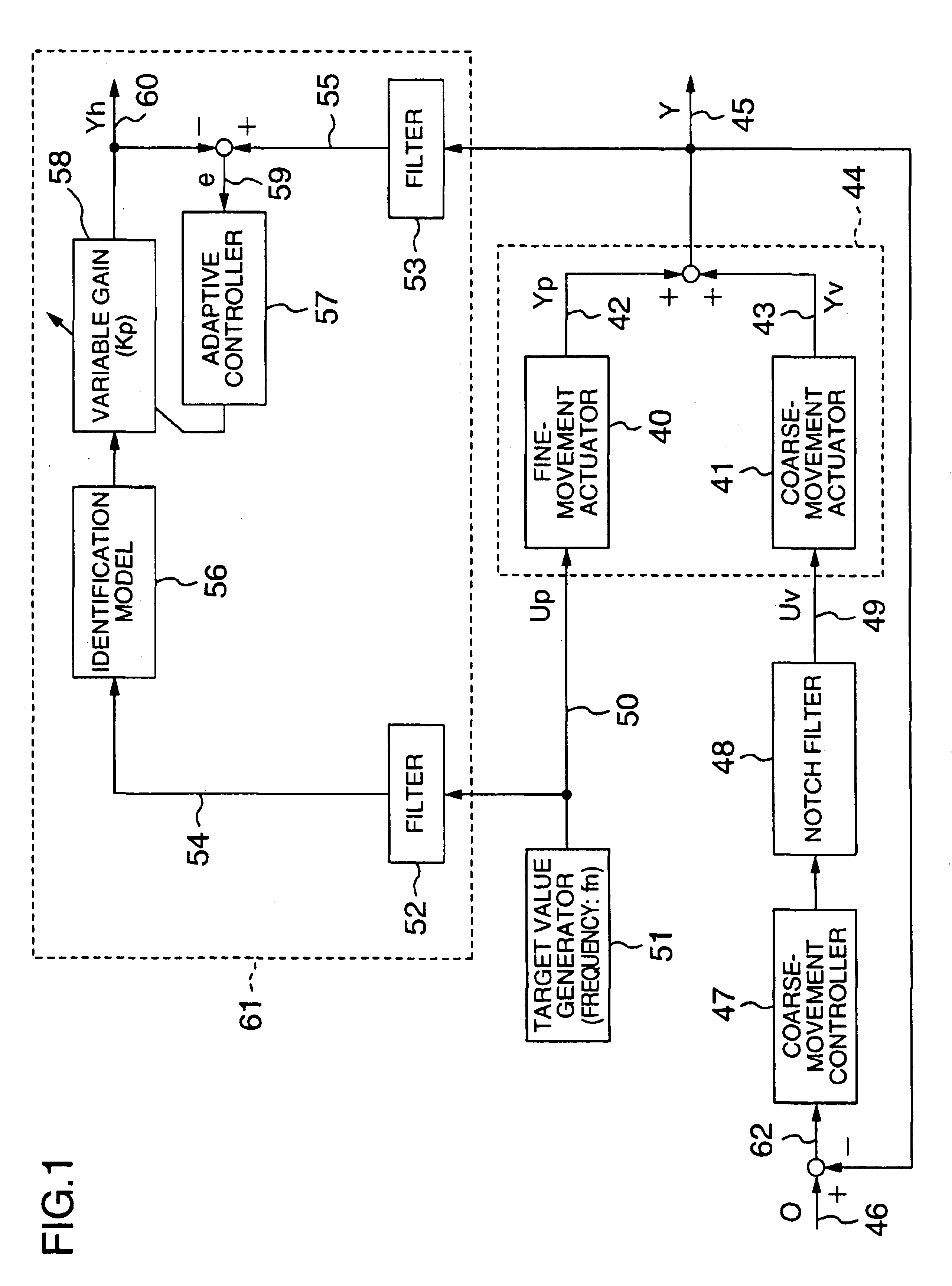
[0012]Preferably, the adaptive identification means is implemented by: an identification model indicating characteristics of the fine-movement actuator; a variable gain indicating gain of the fine-movement actuator to be estimated; an identification model output signal as the product of the identification model and the variable gain; and adaptive control means which controls the variable gain so as to reduce the deviation of the identification model output signal from the head position signal.
[0018]By the present invention, the controller of the fine-movement actuator can be adjusted or redesigned properly based on the gain of the fine-movement actuator estimated with high accuracy, by which high-precision head positioning control can be attained. The high-precision positioning control allows smaller track width (track interval) and higher data density per disk surface, thereby higher storage capacity of the disk storage drive can be realized. Further, since the gain deterioration of the fine-movement actuator can be detected, necessary action or steps can be taken properly and immediately and thereby the reliability of the device can be increased.

Problems solved by technology

On the other hand, there is a certain limit to the increasing of resonance frequency of the actuator mechanism since weight reduction deteriorates the stiffness of the actuator, by which the frequency band of the positioning control system is necessitated to be restricted.
On the other hand, for the estimation of the input-output characteristics of the fine-movement actuator, it is difficult to let the fine-movement actuator operate alone for the positioning without letting the coarse-movement actuator operate, since the stroke of the fine-movement actuator is too small relative to various external perturbations to the actuator.
The method, requiring two measurement steps for the estimation and employing a Fourier-transform technique for the gain estimation, involved problems with estimation time and estimation accuracy.
Further, an external perturbation signal like a sine wave has to be applied to the fine-movement actuator for the estimation, during which data reading / writing by the head becomes impossible.

Method used


Image

  • Positioning control device for two-stage actuator
  • Positioning control device for two-stage actuator
  • Positioning control device for two-stage actuator

Examples


Embodiment Construction

[0029]Referring now to the drawings, a description will be given in detail of preferred embodiments in accordance with the present invention.

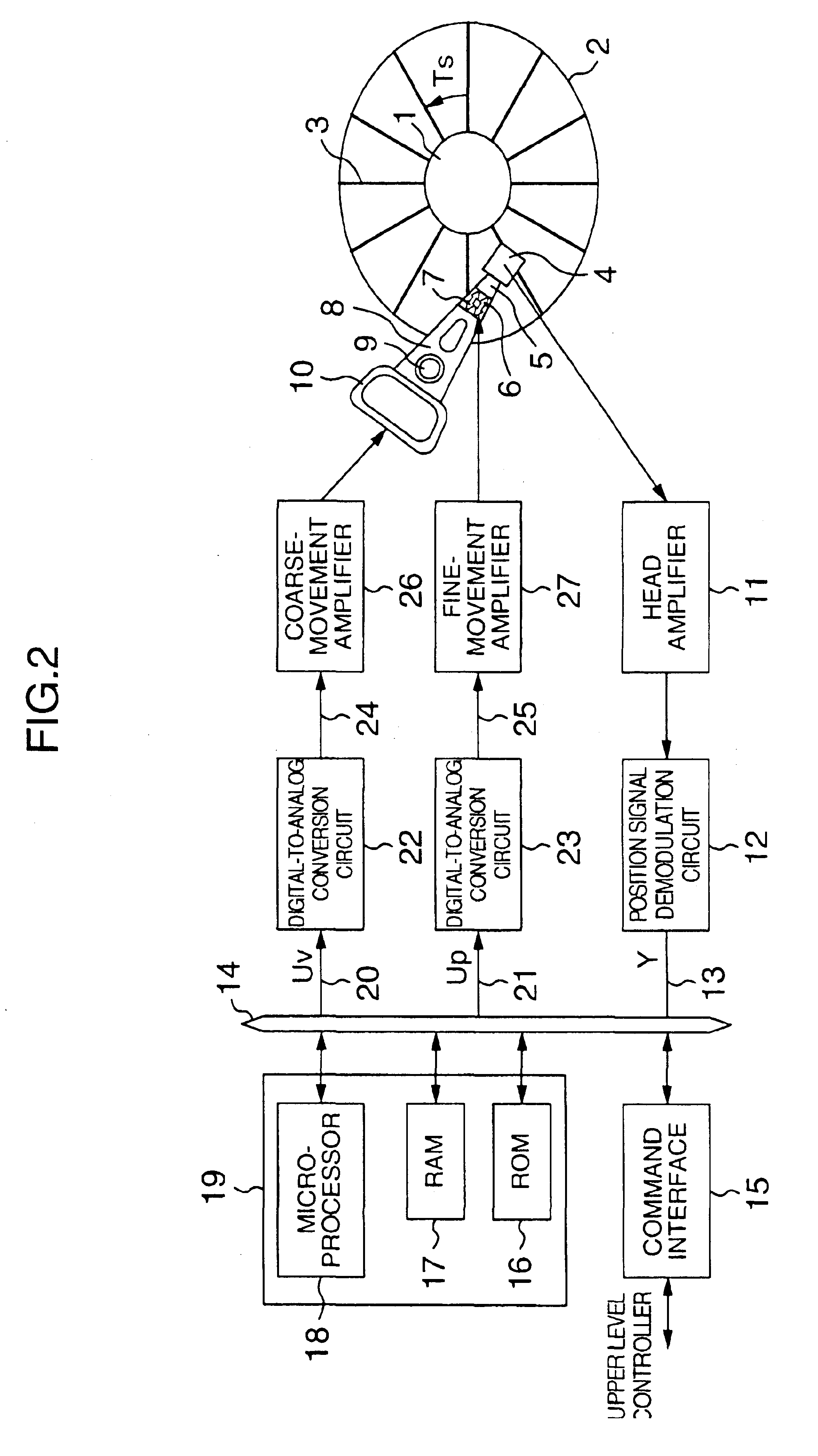
[0030]In consideration of the fact that the two-stage actuator as a controlled system is a two-input one-output system, the present inventors invented a method for eliminating the moving distance of the coarse-movement actuator from the head position signal (output signal) at a specific frequency. By the method, it becomes possible to correctly estimate the input-output characteristics of the fine-movement actuator based on its driving input signal and the head position signal. The first invention will be described first referring to FIGS. 1 through 6B as a first embodiment of the present invention. Following the above invention, the present inventors invented a concrete method for correctly estimating the input-output characteristics of the fine-movement actuator based on the control input signal of the fine-movement actuator and the head posi...


PUM

PropertyMeasurementUnit
widthaaaaaaaaaa
widthaaaaaaaaaa
widthaaaaaaaaaa

Abstract

In a positioning control device for a two-stage actuator having a coarse-movement actuator and a fine-movement actuator, a notch filter having a cutoff frequency fn is provided to a coarse-movement control loop, and the fine-movement actuator is driven by a sine wave of the frequency fn. At the frequency fn, a head position signal becomes identical with an output signal of the fine-movement actuator, by which the gain of the fine-movement actuator can be estimated by an adaptive identification unit with high accuracy based on the control input to the fine-movement actuator and the head position signal.

Description

BACKGROUND OF THE INVENTION[0001]1. Field of the Invention[0002]The present invention relates to disk storage drives such as magnetic disk units and optical disk units in which high-precision head positioning control is realized by letting a fine-movement actuator (of high response and short stroke) and a coarse-movement actuator (of low response and long stroke) operate in cooperation, and in particular, to positioning control technology for such a two-stage actuator by which input-output characteristics of the fine-movement actuator can be estimated and identified.[0003]2. Description of the Related Art[0004]A disk storage drive such as a magnetic disk unit is required to drive its head to a desired track of a disk by an actuator at high speed (seek control) and let the head stay on the desired track with high accuracy (following control) in order to realize high-speed access to information that has been recorded on the disk with high data density. To meet such requirements, it be...

Claims


Application Information

Patent Timeline
Patent Type & Authority Patents(United States)
IPC IPC(8): G11B5/48G11B5/55G11B5/596G11B21/08G11B21/10
CPCG11B5/5526G11B5/4806
Inventor KOBAYASHI, MASAHITONUMASATO, HIDEHIKOOKUYAMA, ATSUSHI
Owner HITACHI GLOBAL STORAGE TECH JAPAN LTD
Learn More