
Thin film magnetic head having multiple layered films determining track width imbedded in an insulating film and method of manufacturing the same

a thin film, magnetic head technology, applied in the direction of magnetic head with metal sheet core, record information storage, instruments, etc., can solve the problems of insufficient pattern resolution, inability to illustrate portions that are compatible with all kinds of magnetic heads, and inability to accurately determine the width of the track. , to achieve the effect of accurate width formation

Inactive Publication Date: 2005-05-24
HITACHI GLOBAL STORAGE TECH JAPAN LTD
View PDF4 Cites 6 Cited by
  • Summary
  • Abstract
  • Description
  • Claims
  • Application Information

AI Technical Summary

Benefits of technology

[0025]The present invention provides a thin film magnetic head that permits accurate formation of the width to determine the track width of the upper magnetic film and a method for manufacturing the same.

Problems solved by technology

However, it goes without said that the unillustrated portions are compatible with all kinds of magnetic heads.
This, however, would make the focal depth shallow, namely narrow the region in focus at the time of pattern formation, and therefore the pattern would not be resolved sufficiently unless the resist film thickness is thin.
This greater thickness of the photoresist in the position where the width to determine the track width is to be formed makes too thick relative to the required plating thickness of the magnetic film and thereby makes it correspondingly more difficult to form a highly accurate pattern.
This makes it necessary to take into consideration fluctuations of the quantity of polishing by CMP or any other method as tolerance, and accordingly prohibits a sufficient reduction in the film thickness of the photoresist.

Method used


Image

  • Thin film magnetic head having multiple layered films determining track width imbedded in an insulating film and method of manufacturing the same
  • Thin film magnetic head having multiple layered films determining track width imbedded in an insulating film and method of manufacturing the same
  • Thin film magnetic head having multiple layered films determining track width imbedded in an insulating film and method of manufacturing the same

Examples


embodiment 2

(Embodiment 2)

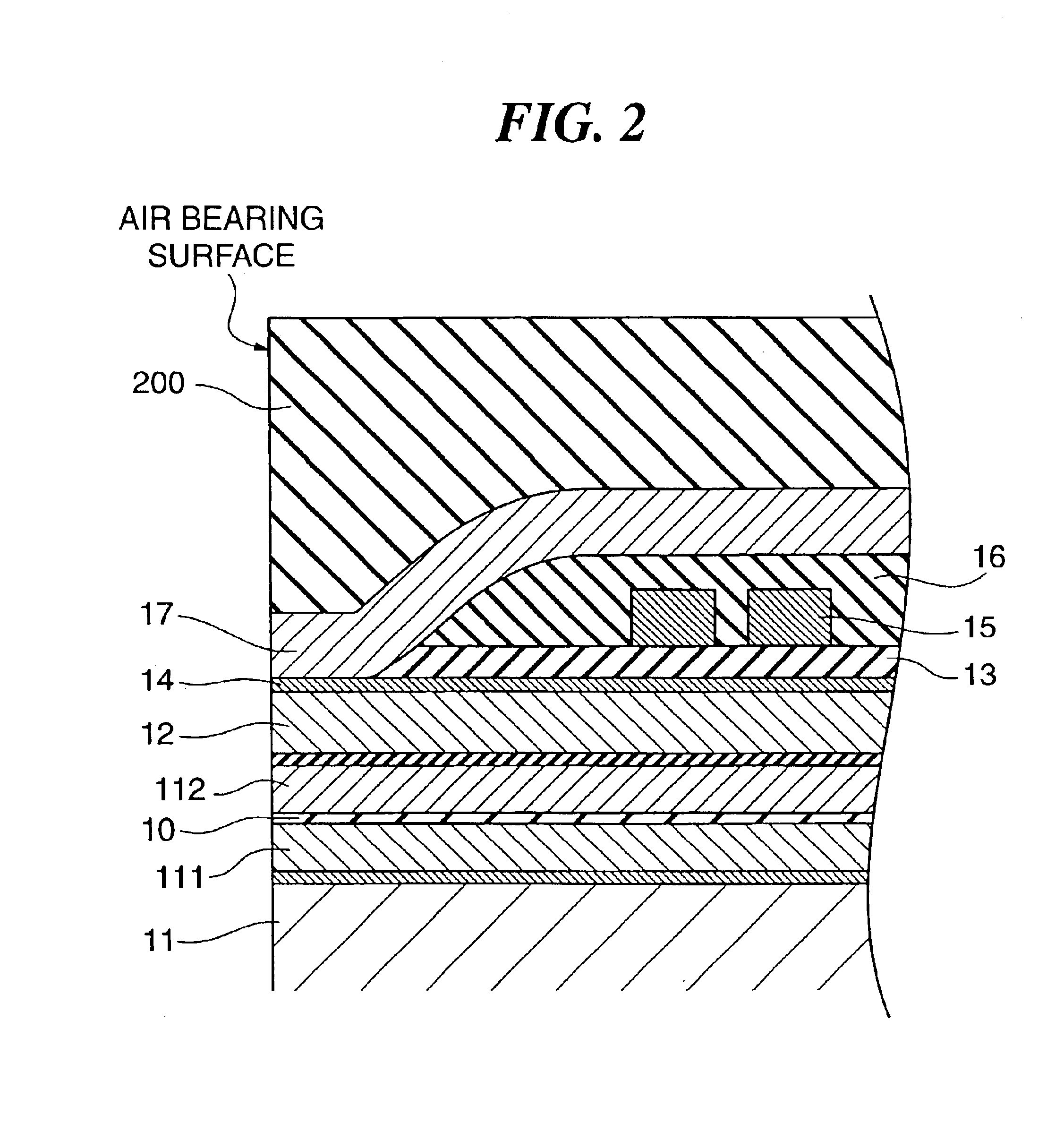
[0076]A sectional view of a thin film magnetic head, which is a second preferred embodiment of the invention, is shown in FIG. 6. As shown in FIG. 6, the thin film magnetic head in this mode of implementing the invention is an example of structure having a single layer of conductor coil in contrast to the first embodiment whose structure has two layers of conductor coils.

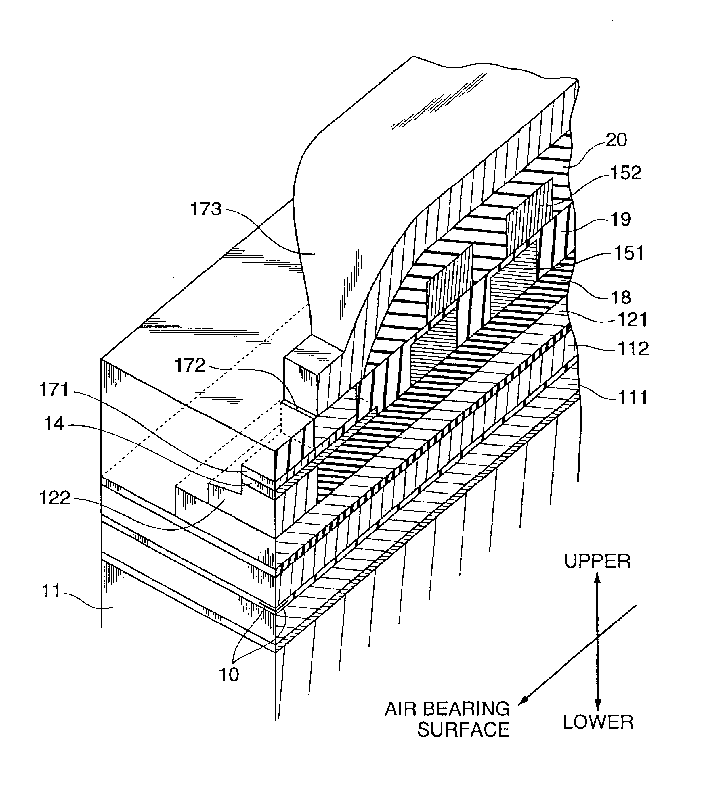
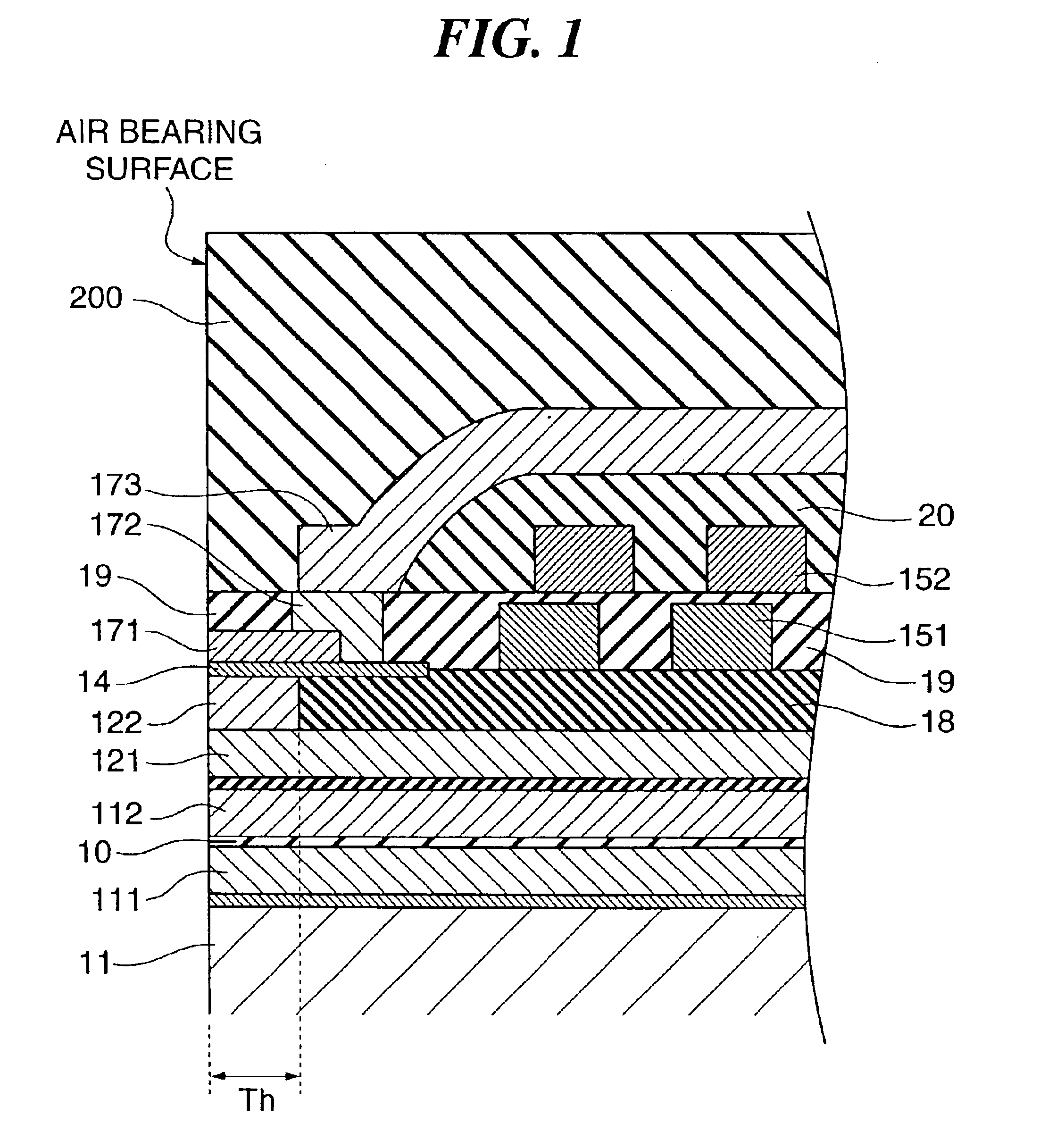
[0077]This drawing illustrates the tip portion of the thin film magnetic head. The description of the read head section is dispensed with because it has the same structure as its counterpart in the first embodiment. In the write head section, the lower first magnetic film 121 and the lower second magnetic film 122 are successively formed. The surface is flattened with the insulating film 18, and the upper first magnetic film 171 is formed to be opposite the lower second magnetic film 122 via the magnetic gap 14.

[0078]The lower second magnetic film 122 and the upper first magnetic film 171 constitute th...

embodiment 3

(Embodiment 3)

[0084]A sectional view of a thin film magnetic head, which is a third preferred embodiment of the invention, is shown in FIG. 8. This thin film magnetic head is structured as a version of the second embodiment in which no insulating film 20 is used. Thus, the step of forming the insulating film 20 shown in FIG. 7I is skipped, resulting in a structure in which the upper third magnetic film 173 is stacked over a flat surface formed by the insulating film 19 and the upper second magnetic film 172.

[0085]This arrangement provides an advantage of reducing the number of steps and simplifying the structure.

embodiment 4

(Embodiment 4)

[0086]FIG. 9 is a sectional view of the essential part of a thin film magnetic head, which is a fourth preferred embodiment of the invention. In this mode of implementing the invention, the first embodiment is applied to a single pole perpendicular write thin film magnetic head. As is the first embodiment, this thin film magnetic head is formed by successively stacking the read head section and the write head section over the substrate 11 consisting of alumina-based ceramics.

[0087]The description of the read head section is dispensed with because its structure is similar to that of the first embodiment. In the write head section, the lower first magnetic film 121 to serve as a return pole is formed, and over its surface is formed the magnetic gap 14. Then is formed the upper first magnetic film 171 which is to constitute a monopole to the lower first magnetic film 121 via the magnetic gap 14. This causes the lower first magnetic film 121 and the upper first magnetic fi...


PUM

PropertyMeasurementUnit
heightaaaaaaaaaa
thicknessaaaaaaaaaa
thicknessaaaaaaaaaa

Abstract

The present invention is to provide a thin film magnetic head intended to increase precision of and to narrow a width which determines a track width of a write thin film magnetic head and to supply a stably high output substantially free from write blurring on a disk, and a method for manufacturing the same. The thin film magnetic head consisting of a magnetic circuit comprising a read head to read information, a lower magnetic film, a magnetic gap and an upper magnetic film formed with a magnetic gap between it and the lower magnetic film; and of a write head comprising a coil positioned between the upper magnetic film and the lower magnetic film and an insulating film for insulting the coil and the upper magnetic film from each other, wherein the upper magnetic film is configured of an upper first magnetic film, an upper second magnetic film and an upper third magnetic film, and the upper first magnetic film is connected to the upper third magnetic film via the upper second magnetic film.

Description

BACKGROUND OF THE INVENTION[0001]1. Field of the Invention[0002]The present invention relates to a thin film magnetic head for use in head disk assemblies (HDAs) such as magnetic disk apparatuses, and more particularly to a thin film magnetic head compatible with high recording density, excelling in recording performance, and a method for manufacturing the same.[0003]2. Description of the Prior Art[0004]In recent years, along with the capacity enlargement of computers, the requirement for higher recording density of magnetic disk apparatuses is increasing more and more. In this connection, an ever narrower width is required for thin film magnetic heads to be mounted on magnetic disk apparatuses, as the width determines the track width of magnetic cores mounted thereon, and the requirement for their manufacturing accuracy is becoming increasingly stringent. Furthermore, the recording performance is also required to be high enough to prevent blurred recording of signals onto the magne...

Claims


Application Information

Patent Timeline
Patent Type & Authority Patents(United States)
IPC IPC(8): G11B5/127G11B5/39G11B5/31
CPCG11B5/1278G11B5/3906Y10T29/49046
Inventor OKAI, TETSUYAMORIJIRI, MAKOTOMARUYAMA, YOJIETOH, KIMITOSHI
Owner HITACHI GLOBAL STORAGE TECH JAPAN LTD
Learn More