Thermal diffusion apparatus

a technology of diffusion apparatus and heat dissipation chamber, which is applied in the direction of cooling/ventilation/heating modification, semiconductor/solid-state device details, semiconductor devices, etc., can solve the problems of reducing the efficiency and performance of electronic components in an elevated temperature environment, effectively removing relatively high levels of thermal energy away from a relatively small area, and limited thermal energy of conventional heat sink devices. achieve the effect of improving heat dissipation efficiency, reducing heat loss, and increasing heat loss

Inactive Publication Date: 2005-05-24
TCLAD INC
View PDF28 Cites 64 Cited by
  • Summary
  • Abstract
  • Description
  • Claims
  • Application Information

AI Technical Summary

Benefits of technology

[0012]By means of the present invention, an apparatus is provided for enhanced heat transfer from a heat-generating electronic component. In particular, the thermal diffusion apparatus of the present invention both accelerates and renders more efficient the heat transfer from a heat generating device to a heat sink by quickly diffusing thermal energy away from a relatively localized thermal contact point adjacent the heat generating device to the heat sink and to portions of a diffusion apparatus distal to such localized thermal contact point. Thus, the apparatus of the present invention more effectively distributes thermal energy radially and within a planar boundary, such that a significantly greater extent of an operably coupled heat sink may be effectively utilized to dissipate such thermal energy from the heat generating device.

Problems solved by technology

Such thermal diffusion devices are important to electronic applications, in that many electronic components lose efficiency and performance in an elevated temperature environment.
A common problem encountered in conventional heat sink devices is in effectively removing relatively high levels of thermal energy away from a relatively small area.
Conventional heat sink devices, however, are limited in the amount of thermal energy they are able to transport away from the heat source by their respective thermal conductivities, as well as the thermal contact area between the heat sink and the heat-generating device.
In many cases, heat sinks carry nowhere near their respective heat transfer capacities, due to the fact that only a small portion of the respective heat sink bodies are utilized in transferring thermal energy away from the heat-generating device.
In other words, the relatively small heat-generating device, such as a semi-conductor, creates a thermal footprint in the thermally-coupled heat sink, which thermal footprint has an area substantially similar to the thermal contact area between the heat sink and the heat-generating device.
In most cases, however, conventional heat sinks are significantly larger than electronic components from which thermal energy is transferred to effectively handle and dissipate the heat generated therefrom.
Such a focused location of maximum heat transfer generally compromises the overall effectiveness of the heat sink, in that only the focused area of the heat sink carries and transfers its maximum capacity rate of thermal energy, while the remainder of the heat sink carries and transfers far less than its thermal transfer capacity.
Such performance, however, typically results in an increased degree of thermal output from the respective electronic device.
Conventional heat sinks often times become “saturated” with thermal energy at certain focused locations, and therefore fail to adequately draw a sufficient amount of thermal energy from such high-output electronic components so as to maintain a relatively steady-state temperature operating environment for such electronic components.
However, such devices commonly utilize a relatively large amount of expensive, highly thermally-conductive material such as diamond, and are not useful in a wide variety of heat-sinking applications.

Method used


Image

  • Thermal diffusion apparatus
  • Thermal diffusion apparatus
  • Thermal diffusion apparatus

Examples


example i

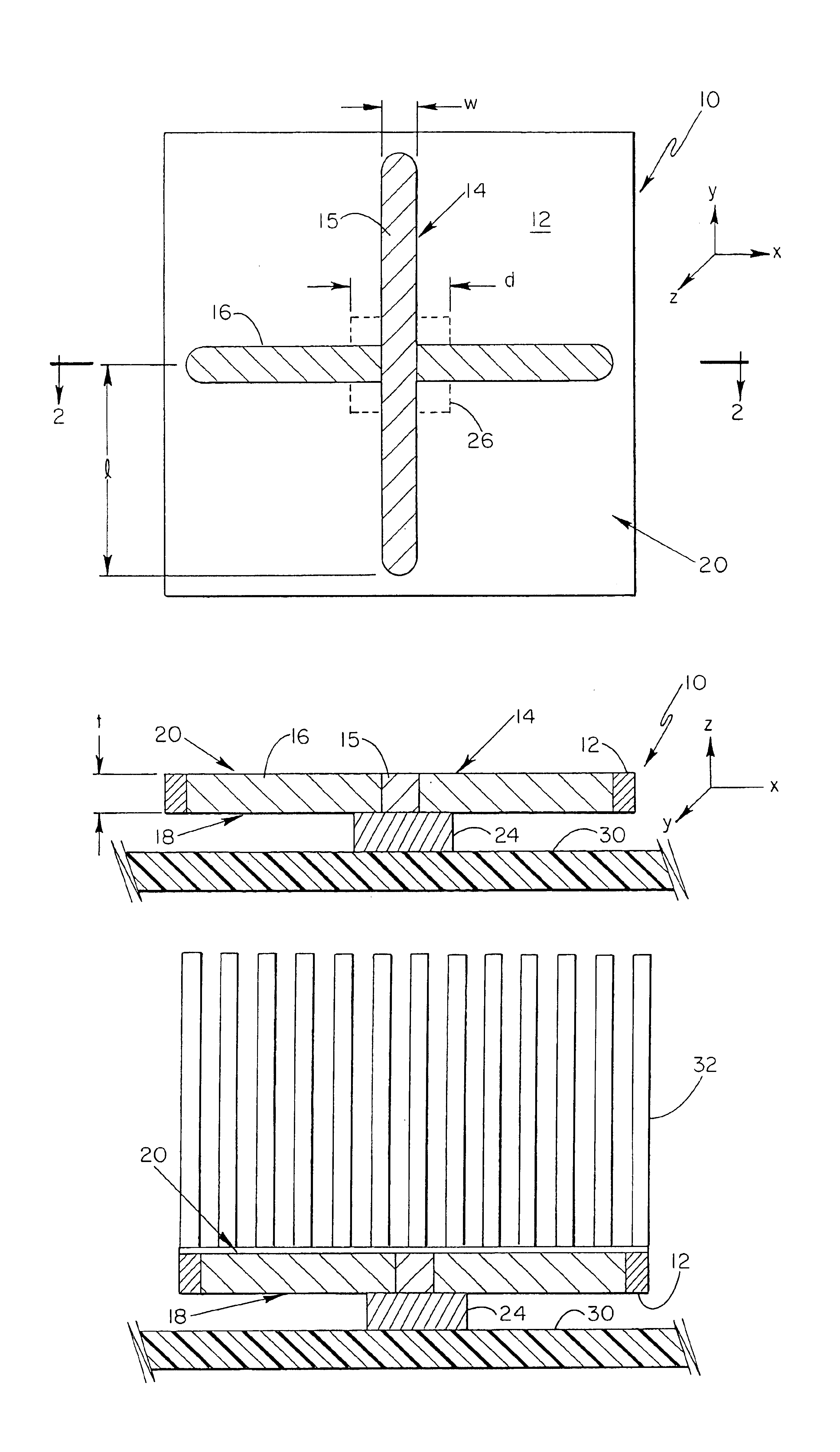
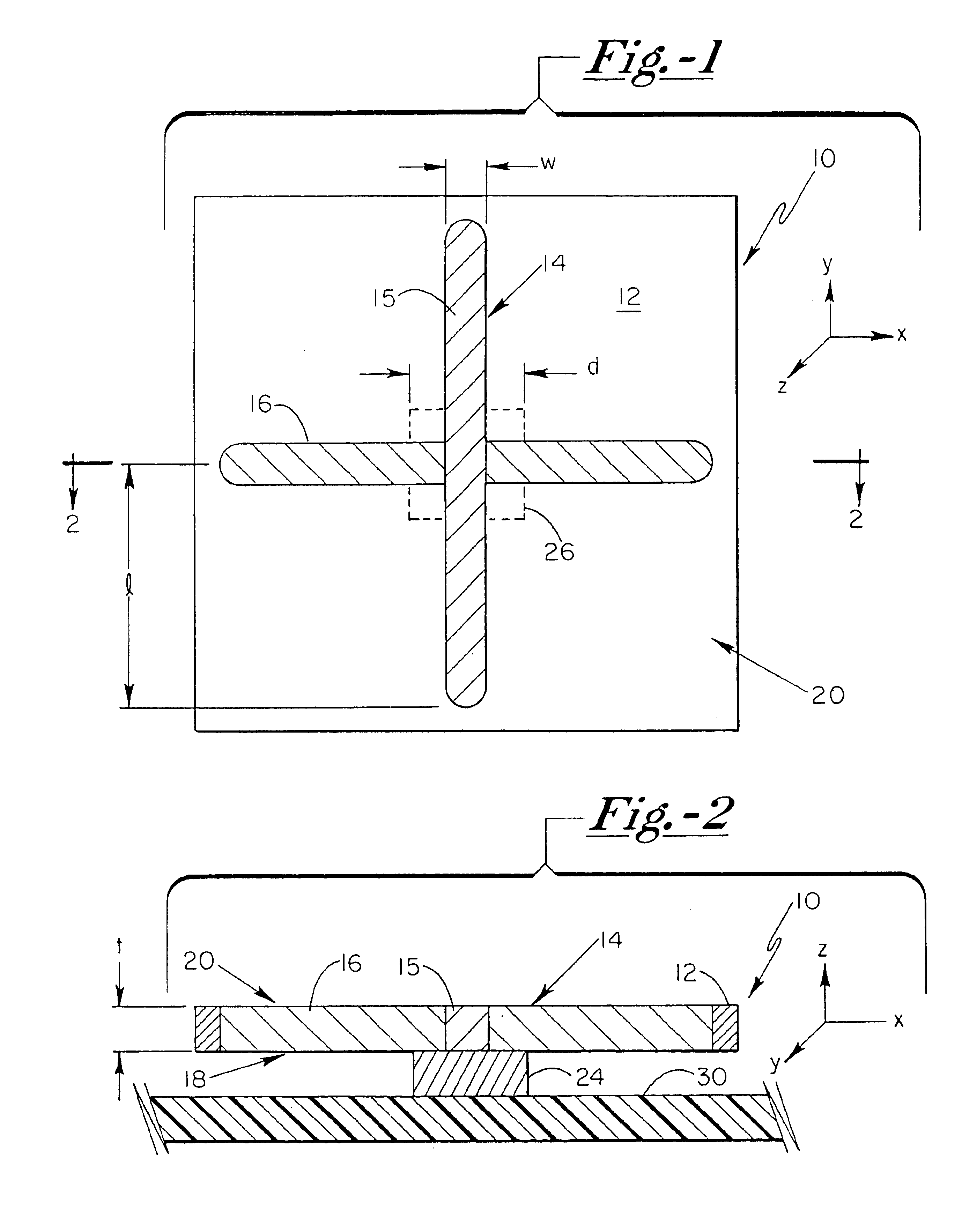
[0036]To form the thermal diffusion apparatus, a 1.5″×1.5″×0.08″ copper substrate and 1″×0.08″×0.08″ highly oriented pyrolytic graphite insert portions were obtained. Appropriately-sized slots were milled in the copper substrate, such that two pyrolytic graphite inserts were positioned and secured in the resultant opening within the copper substrate with Bergquist Sterling 7500™ thermally conductive grease acting as the interface between the inserts and the copper substrate. The inserts were positioned in a substantially perpendicular “cross” orientation, with the respective mid-points of the insert portions substantially intersecting with one another. The insert portions were oriented in the copper substrate such that a highly thermally conductive direction characteristic of the insert portions were oriented in a plane perpendicular to a plane of the substrate.

[0037]A Motorola IRF-840, TO-220 package, acting as the heat source, was operated at 60 watts and coupled to the thermal di...

example ii

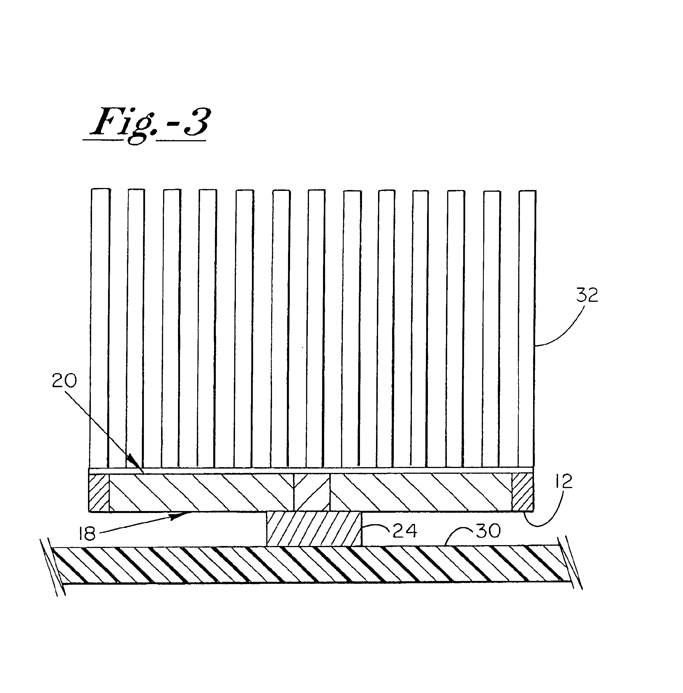
[0041]Thermal diffusion structures with integrated finned heat sink configurations were provided. The heat sink devices were fabricated from aluminum and were 2.4″×3.2″×0.75″ in size, with one of the heat sink devices having highly oriented pyrolytic graphite insert portions in an upper side thereof. The heat sink device incorporating insert portions included two such portions, each of which were 1″×0.12″×0.08″ in dimension, the two insert portions being positioned along the upper surface of the heat sink in a substantially perpendicular “cross” pattern, with the mid-points of each of the insert portions substantially intersecting with one another. To assist in removing heat from the heat sink devices, a 9.18 CFM maximum air flow fan was operated at 4500 rpm to direct such air flow across the fins of the heat sink elements.

[0042]TO-220 packages were secured to respective upper surfaces of the heat sink structures via Bergquist Sterling 7500™ grease. The TO-220 package was placed on ...


PUM


Abstract

An apparatus for operably conveying heat away from a heat source includes a thermally conductive substrate having a thickness defining a planar boundary thereof, and an insert portion disposed in the substrate and being positioned so as not to extend beyond the planar boundary. The insert portion is a material having a thermal conductivity value of at least 1.5 times that of the substrate material along at least two axial directions, with one of such axial directions extending substantially perpendicularly to first and second opposed sides of the substrate.

Description

FIELD OF THE INVENTION[0001]This invention relates to thermal draw devices generally and more particularly to a heat spreader apparatus for efficiently removing and diffusing heat from a localized source to a relatively large surface area body for subsequent dissipation therefrom through various heat exchange techniques. In particular, the present invention relates to highly thermally conductive materials utilized as inserts into conventional thermal diffusion bodies in a specific pattern so as to greatly expedite thermal diffusion from a localized heat source.BACKGROUND OF THE INVENTION[0002]In many electrical applications, and particularly in semi-conductor systems, devices are utilized for assisting in drawing excess heat away from the heat-generating device, such as the microprocessor semi-conductor. Such thermal diffusion devices are important to electronic applications, in that many electronic components lose efficiency and performance in an elevated temperature environment. A...

Claims


Application Information

Patent Timeline
Patent Type & Authority Patents(United States)
IPC IPC(8): H01L23/50H01L23/48H05K7/20F28FH01L23/367H01L23/373
CPCH01L23/367H01L23/3736H01L23/3737H01L2924/3011H01L2924/0002H01L2924/00H05K7/20
Inventor MISRA, SANJAY
Owner TCLAD INC
Why Eureka
Try Eureka