Emission control system with catalyst warm-up speeding control

a technology of emission control system and catalyst, which is applied in the direction of electrical control, machine/engine, exhaust treatment electric control, etc., can solve the problems of inability to reveal the cause of a detected abnormality, the engine is operated in an abnormal state, and the inability to accurately diagnose the abnormality, etc., to achieve the effect of reducing the quantity of exhaust emissions after the start of the engine, increasing the amount of heat exhausted by the engine, and high degree of reliability

Inactive Publication Date: 2005-05-31
DENSO CORP
View PDF12 Cites 94 Cited by
  • Summary
  • Abstract
  • Description
  • Claims
  • Application Information

AI Technical Summary

Benefits of technology

[0012]It is another object of the present invention to provide a new emission control system capable of determining existence of an abnormality of a catalyst warming up speeding control.
[0036]The intake air volume and the air-fuel ratio themselves are each a parameter for changing the amount of heat exhausted by the engine or the amount of heat supplied to the catalyst. It is thus possible to determine whether the amount of heat exhausted by the engine during the control to speed an operation to warm up the catalyst is sufficient or insufficient for speeding an operation to warm up the catalyst, that is, whether the emission control system is functioning normally or abnormally, by using the intake airflow rate parameter and the air-fuel ratio parameter. Thus, it is possible to make a diagnosis of the emission control system in order to determine whether or not an abnormality exists in the emission control system with a high degree of precision. In addition, since it is not necessary to install a new sensor for detecting a temperature of the catalyst, a demand for reduction of the cost can be met.

Problems solved by technology

However, an accurate diagnosis is hard to carry out.
By basing the determination on only one of the engine revolution speed and the ignition timing, however, the determination may produce an incorrect result.
Thus, even if an abnormality is determined to exist, the engine is operated in an abnormal state caused by a late operation to warm up the catalyst.
Furthermore, the control techniques to speed the operation to warm up the catalyst and the diagnoses of a function to speed the operation to warm up the catalyst, which are disclosed in Japanese patent JP-P2001-132438A and Japanese patent JP-P2001-132526A, have a problem of an inability to reveal a cause of a detected abnormality.
Moreover, from another aspect, the disclosed art is considered to raise a problem that the catalyst may return back to an inactive state after being activated in some cases.

Method used


Image

  • Emission control system with catalyst warm-up speeding control
  • Emission control system with catalyst warm-up speeding control
  • Emission control system with catalyst warm-up speeding control

Examples


first embodiment

[0095

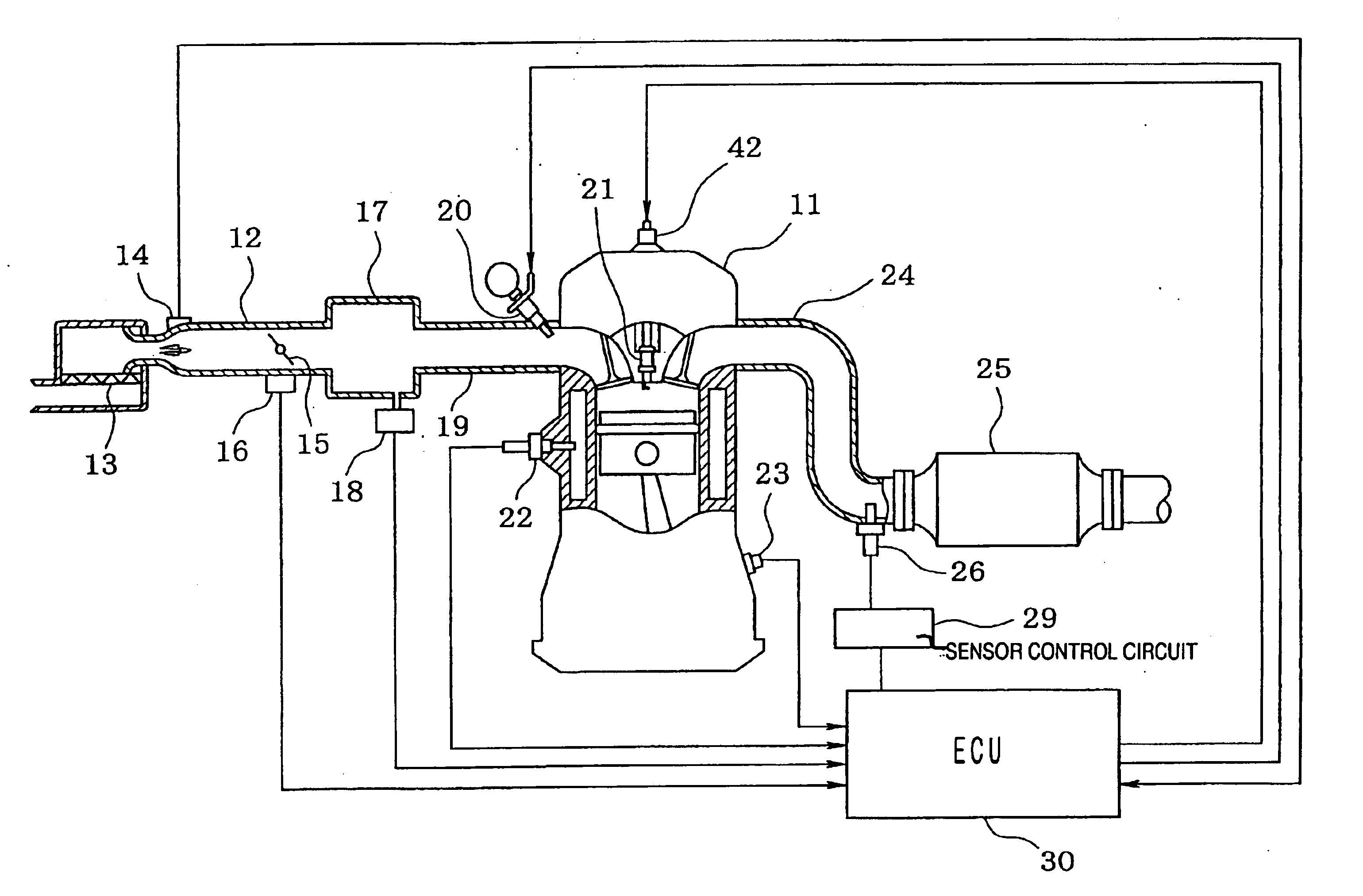
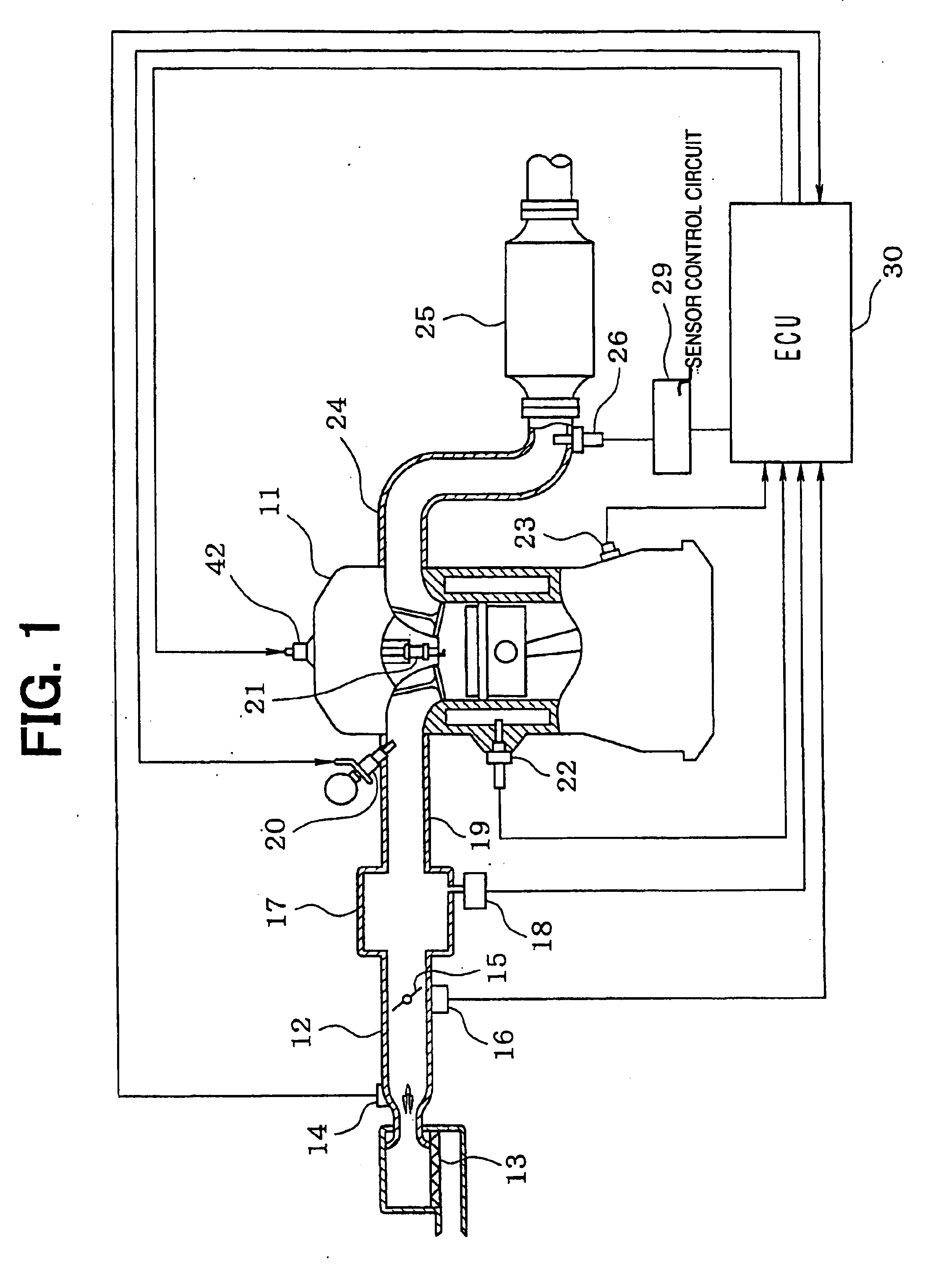
[0096]Some preferred embodiments of the present invention are explained by referring to diagrams as follows. First of all, a simple and plain configuration of an engine control system is described by referring to FIG. 1. At the start end of the upstream portion of an intake pipe 12 employed in an engine 11 serving as an internal combustion engine, an air cleaner 13 is provided. On the downstream side of the air cleaner 13, an air flow meter 14 is provided for detecting an intake air volume. On the downstream side of the air flow meter 14, there are provided a throttle valve 15 and a throttle-opening sensor 16 for detecting a throttle opening.

[0097]Furthermore, on the downstream side of the throttle valve 15, a surge tank 17 is provided. On the surge tank 17, an intake-manifold-pressure sensor 18 is provided for detecting an intake-manifold pressure. In addition, on the surge tank 17, there is provided an intake manifold 19 for introducing air into each cylinder of the engine 11...

second embodiment

[0166

[0167]Next, a second embodiment of the present invention is explained. The elements of the second embodiment identical with their respective counterparts employed in the first embodiment are denoted by the same reference numerals as the counterparts, and explanation of the identical elements is not given.

[0168]FIG. 17 is a diagram showing the configuration of an emission control system implemented by the second embodiment. The catalyst 25 is a three way catalyst. On the exhaust pipe 24 on the upstream side of the catalyst 25, a sensor 51 is provided. On the exhaust pipe 24 on the downstream side of the catalyst 25, on the other hand, a sensor 52 is provided. The sensors 51 and 52 are each an exhaust gas component detection means for detecting a component of exhaust gas. Specifically, the sensors 51 and 52 can each be a sensor capable of detecting a concentration of a component of exhaust gas such as oxygen contained in the exhaust gas, a sensor capable of detecting an air-fuel ...

third embodiment

[0202

[0203]Next, a third embodiment of the present invention is explained. The configuration elements of the third embodiment identical with their respective counterparts employed in the first and second embodiments are denoted by the same reference numerals as the counterparts, and the explanation of the identical elements is not given.

[0204]FIG. 22 is a diagram showing the configuration of an emission control system implemented by the third embodiment. The engine 11 is a V-type engine. The exhaust pipe comprises an exhaust pipe 24a for the right bank, an exhaust pipe 24b for the left bank and an exhaust pipe 24c for joining the exhaust pipe 24a to the exhaust pipe 24b. A catalyst 25 is provided on the exhaust pipe 24c. A sensor 52 is provided on the downstream side of the catalyst 25. The sensor 25 is an O2 sensor or an A / F sensor. A signal output by the sensor 52 can be used in correction of a target air-fuel ratio in feedback control of the air-fuel ratio. A sensor 26a is provid...


PUM


Abstract

An emission control system has a catalyst and a sensor responding to a component of exhaust gas. In order to speed warming up the catalyst, the emission control system increases the amount of heat dissipated by exhaust gas. A diagnosis of the emission control system is carried out by determining whether the amount of heat dissipated by exhaust gas is sufficient or insufficient. The amount of heat dissipated by exhaust gas is represented by the length of time to an activated state of the sensor. In the diagnosis, the amount of heat generated by a heater provided in the sensor is taken into consideration.

Description

CROSS REFERENCE TO RELATED APPLICATION[0001]This application is based on Japanese Patent Applications No. 2001-317588 filed on Oct. 16, 2001, No. 2001-318240 filed on Oct. 16, 2001, No. 2001-338970 filed on Nov. 5, 2001, No. 2001-338971 filed on Nov. 5, 2001, No. 2001-338972 filed on Nov. 5, 2001, No. 2001-338973 filed on Nov. 5, 2001, and No. 2002-223337 filed on Jul. 31, 2002 the contents of which are incorporated herein by reference.BACKGROUND OF THE INVENTION[0002]1. Field of the Invention[0003]The present invention relates to an emission control system that has at least one catalyst disposed in an exhaust passage for purifying exhaust gas, specifically the system speeds catalyst warm-up and diagnoses the catalyst warm-up speeding function.[0004]2. Related Art[0005]As an apparatus for purifying exhaust gas discharged by an internal combustion engine (referred to hereafter simply as an engine), there has been known an emission control system having a three way catalyst converter ...

Claims


Application Information

Patent Timeline
Patent Type & Authority Patents(United States)
IPC IPC(8): F01N3/22F01N3/20F02D41/14F02D41/02F01N11/00F01N7/00F01N7/04F01N7/02F01N13/02F01N13/04
CPCF01N3/2006F01N13/011F01N11/00F01N11/007F02D41/0255F02D41/1494F02D41/1496F01N13/0093F01N13/009F01N3/22F01N2550/02F01N2550/14F01N2900/0422F02D41/1456F02D2041/2058Y02T10/26Y02T10/47Y02T10/12Y02T10/40
Inventor MORINAGA, SYUJIROIIDA, HISASHIMAJIMA, YOSHIHIROOKA, TATSUYAICHIKAWA, AKIRAWAKAHARA, KEIJITSUTSUMI, MASAYUKIMAEJI, HIDEYUKIYAMADA, MASAKAZUTAKAHASHI, TAKANORIYAMASHITA, YUKIHIRO
Owner DENSO CORP
Why Eureka
Try Eureka