Screw compressor

a screw compressor and compressor technology, applied in the field of screw compressors, can solve problems such as stability and sealing

Inactive Publication Date: 2005-05-31
BITZER KUEHLMASCHINENBAU GMBH
View PDF13 Cites 12 Cited by
  • Summary
  • Abstract
  • Description
  • Claims
  • Application Information

AI Technical Summary

Benefits of technology

[0006]The provision of such a damper channel provides the possibility of reducing the pressure oscillations or pulsations occurring at the inlet.
[0043]In particular, it is of advantage in this case that the effect of the damper channel is ensured by no accumulations of oil forming at its mouth opening facing the outer inlet.

Problems solved by technology

In the case of screw compressors of this type there is the problem that the compression spaces enclosed by the screw rotors and screw rotor bores moving past the inlet cause pressure oscillations or pulsations, which propagate into the pipeline system of the supercooling circuit and lead to noise and possibly also to problems in terms of stability and sealing.

Method used


Image

  • Screw compressor
  • Screw compressor
  • Screw compressor

Examples


Embodiment Construction

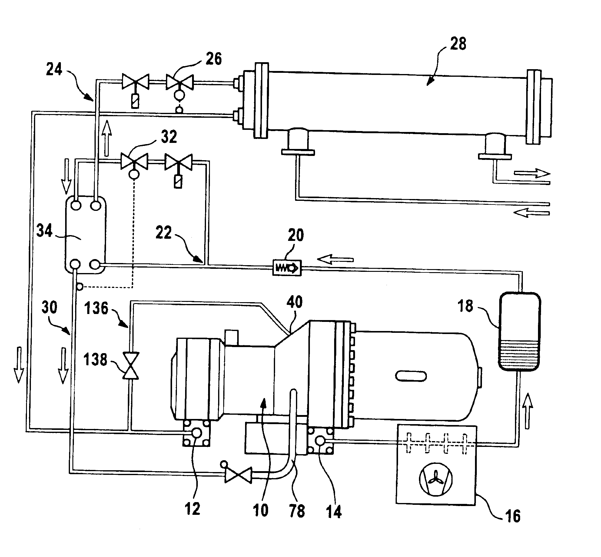
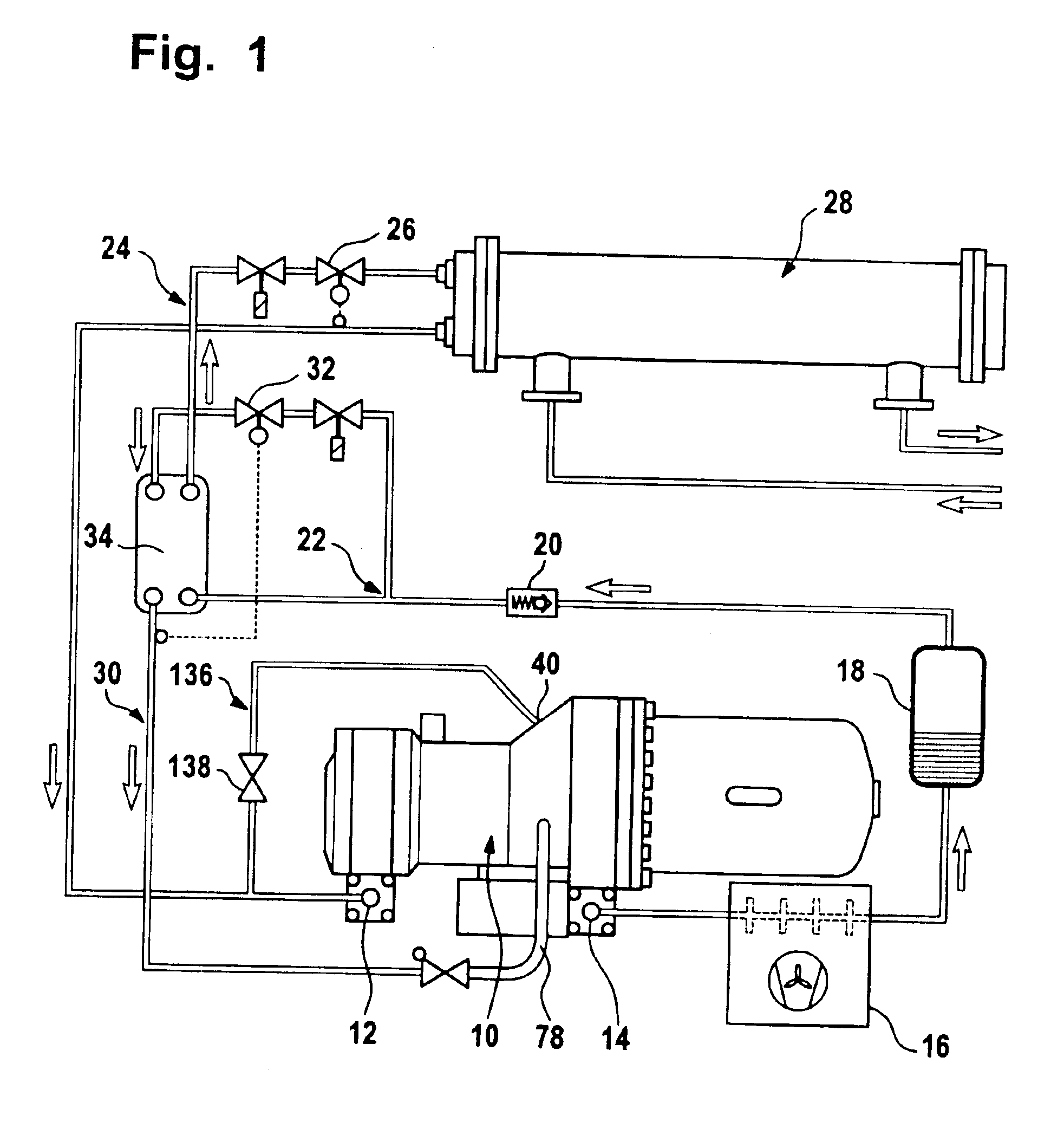
[0050]A first exemplary embodiment of a screw compressor according to the invention, represented in FIG. 1, comprises a compressor casing, which is designated as a whole by 10 and on which a suction connection 12 and a pressure connection 14 are provided, refrigerant being sucked in at the suction connection 12 and compressed refrigerant being delivered at the pressure connection 14.

[0051]The compressed refrigerant delivered at the pressure connection 14 is first fed to a condenser 16 and passes from the condenser 16 into an intermediate store 18 for liquid refrigerant. After the intermediate store 18, the condensed refrigerant flows through a non-return valve 20 and a branch 22, from which a cooling circuit 24 leads further to an expansion valve 26 and an evaporator 28, and then back again from the evaporator 28 to the suction connection 12.

[0052]Provided in addition to the cooling circuit 24 is a supercooling circuit 30, which branches off from the cooling circuit 24 at the branch...


PUM


Abstract

In order to provide a screw compressor comprising two screw rotors which are disposed in screw rotor bores in a compressor casing and which compress a refrigerant entering at a refrigerant inlet and discharge it at a refrigerant outlet, and comprising an inlet provided in the compressor casing for refrigerant which is coming from a subcooling circuit and is passed to the inlet in a system of lines, the inlet being disposed in such a way that it opens out into compression spaces enclosed by the screw rotors and screw rotor bores, in which compressor the pressure oscillations or pulsations occurring at the inlet propagate as little as possible to the pipeline system of the subcooling circuit outside the compressor casing, it is proposed that the inlet is preceded by a damper channel which is associated with the system of lines and in which refrigerant from the subcooling circuit is present.

Description

[0001]The present disclosure relates to the subject matter disclosed in German application No. 102 42 139.0 of Sep. 3, 2002, which is incorporated herein by reference in its entirety and for all purposes.BACKGROUND OF THE INVENTION[0002]The invention relates to a screw compressor, comprising two screw rotors which are disposed in screw rotor bores in a compressor casing and which compress a refrigerant entering at a refrigerant inlet and discharge it at a refrigerant outlet, and comprising an inlet disposed in the compressor casing for refrigerant which is coming from a supercooling circuit and is passed to the inlet via a system of lines, the inlet being disposed in such a way that it opens out into compression spaces enclosed by the screw rotors and screw rotor bores.[0003]In the case of screw compressors of this type there is the problem that the compression spaces enclosed by the screw rotors and screw rotor bores moving past the inlet cause pressure oscillations or pulsations, ...

Claims


Application Information

Patent Timeline
Patent Type & Authority Patents(United States)
IPC IPC(8): F04C18/16F04C29/00F04C23/00F04C28/12
CPCF04C18/16F04C29/0035F04C29/0007F04C28/12F04C23/008
Inventor ROELKE, STEPHANHOSSNER, KLAUS
Owner BITZER KUEHLMASCHINENBAU GMBH
Why Eureka
Try Eureka