Missile fire control system

Inactive Publication Date: 2005-05-31
RAYTHEON CO
View PDF9 Cites 3 Cited by
  • Summary
  • Abstract
  • Description
  • Claims
  • Application Information

AI Technical Summary

Benefits of technology

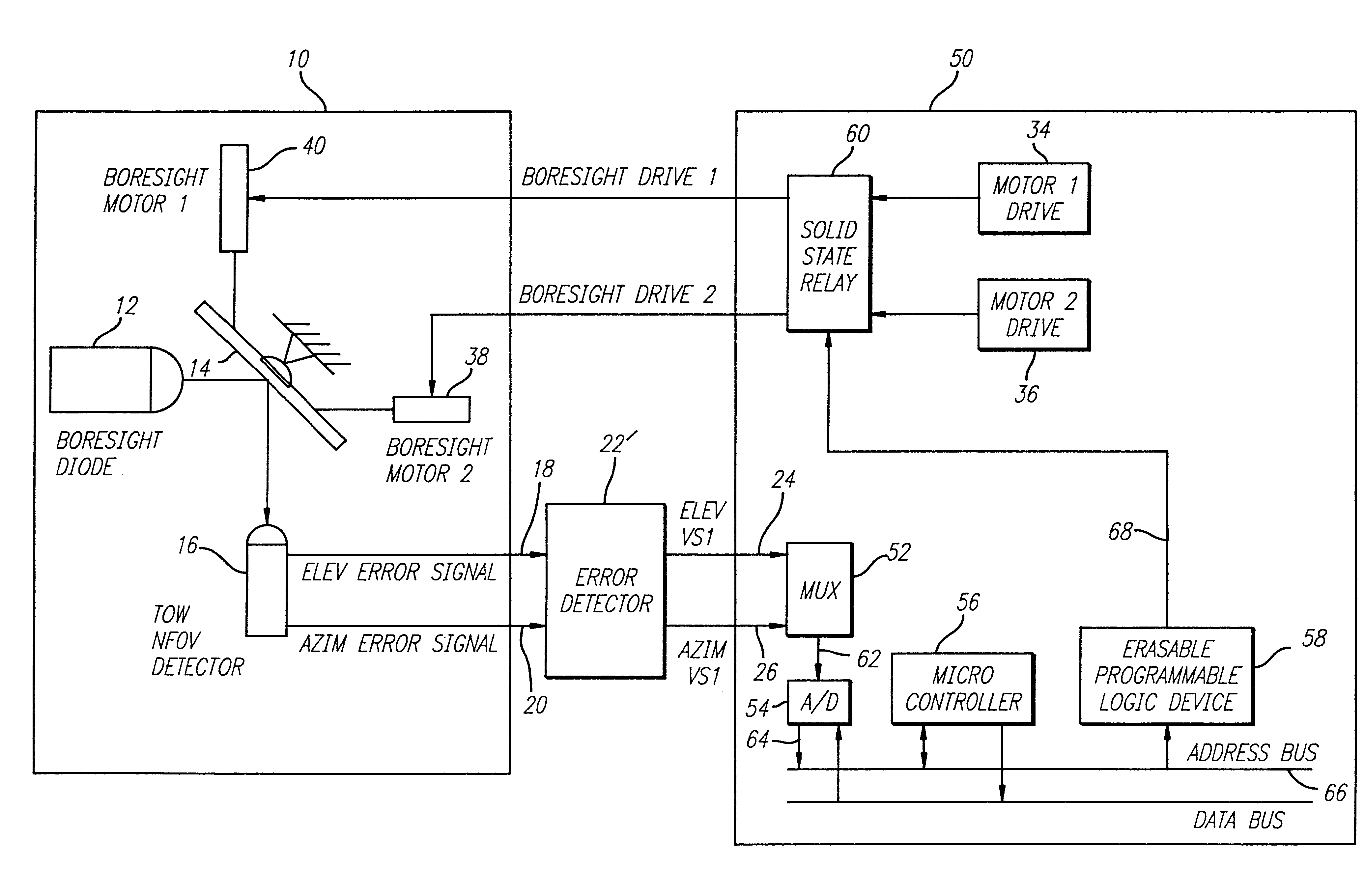
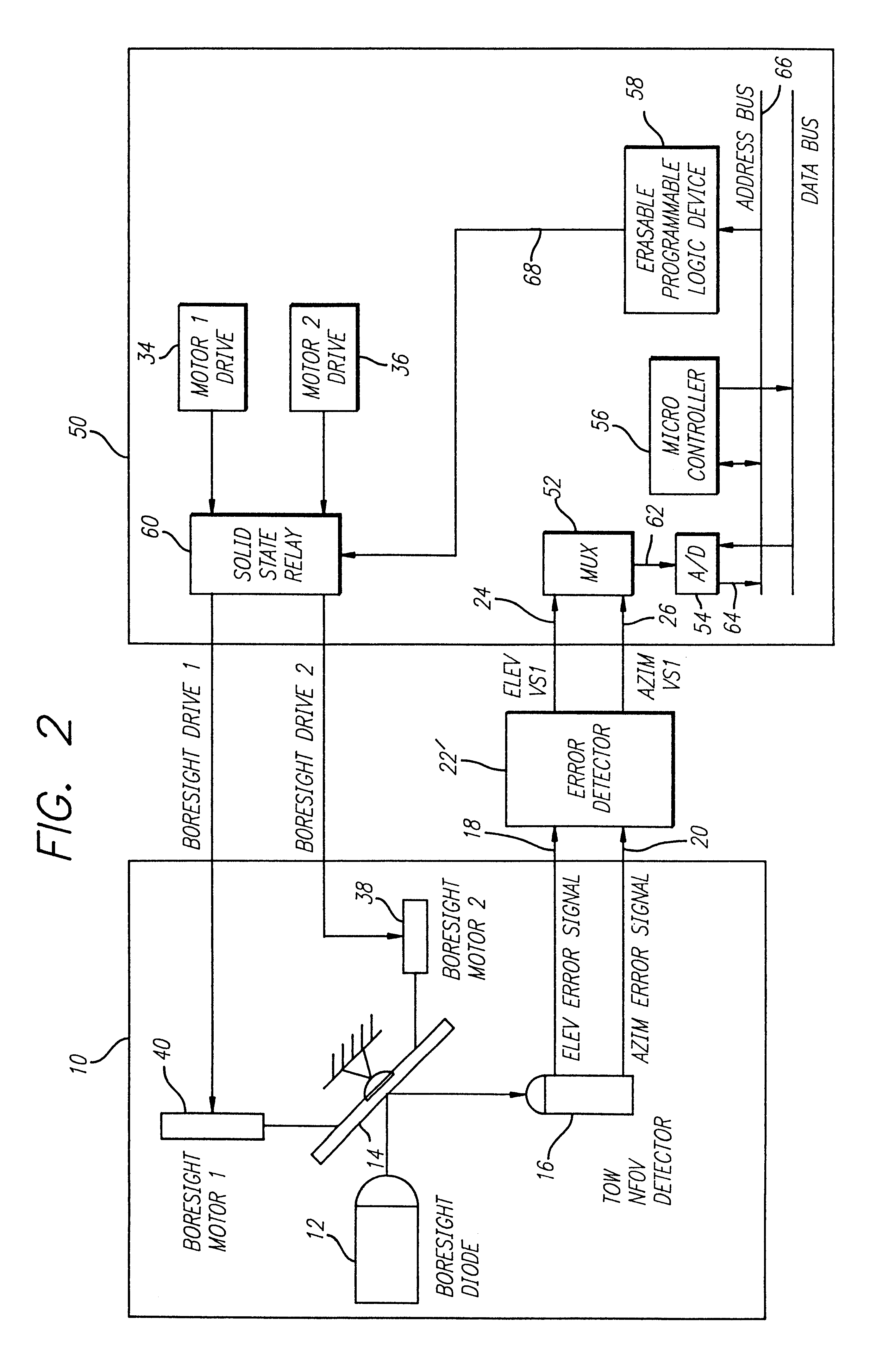
[0009]The need in the art is addressed by the improved missile fire control system of the present invention. In the illustrative embodiment, the inventive system is adapted for use with TOW missile systems and includes a conventional telescope cluster assembly for generating target position signals. The telescope cluster assembly includes a mirror for directing the line-of-sight of the telescope and a detector for providing line-of-sight error signals. A motor is provided for controlling the mirror in response to a control signal provided by a processor. The processor operates on the line-of-sight error signals to eliminate angular noise and to provide the control signal in response thereto.
[0010]In a more specific implementation, a digital error detector receives and processes target position signals from the telescope cluster assembly. The processed signals are then fed to a stabilization control amplifier, where during boresight alignment, a microcontroller steps through a set of instructions that eliminate angular noise from the target position signals. The stabilization control amplifier subsequently provides feedback to the telescope cluster assembly for adjusting the line-of-sight in the telescope cluster assembly.

Problems solved by technology

The electrical subsystems of conventional TOW missiles are not designed to be compatible with new devices such as laser target designators.
As a result, components necessary for replacement are becoming increasingly difficult to obtain.
In addition, conventional TOW fire control circuitry is plagued with noise.
Noise filtering was limited due to stability requirements of the boresight control loop.

Method used


Image

  • Missile fire control system
  • Missile fire control system
  • Missile fire control system

Examples


Embodiment Construction

[0016]Illustrative embodiments and exemplary applications will now be described with reference to the accompanying drawings to disclose the advantageous teachings of the present invention.

[0017]The invention is described below in reference to the accompany drawings in which like reference numerals denote like parts. While the present invention is described herein with reference to illustrative embodiments for particular applications, it should be understood that the invention is not limited thereto. Those having ordinary skill in the art and access to the teachings provided herein will recognize additional modifications, applications and embodiments within the scope thereof and additional fields in which the present invention would be of significant utility.

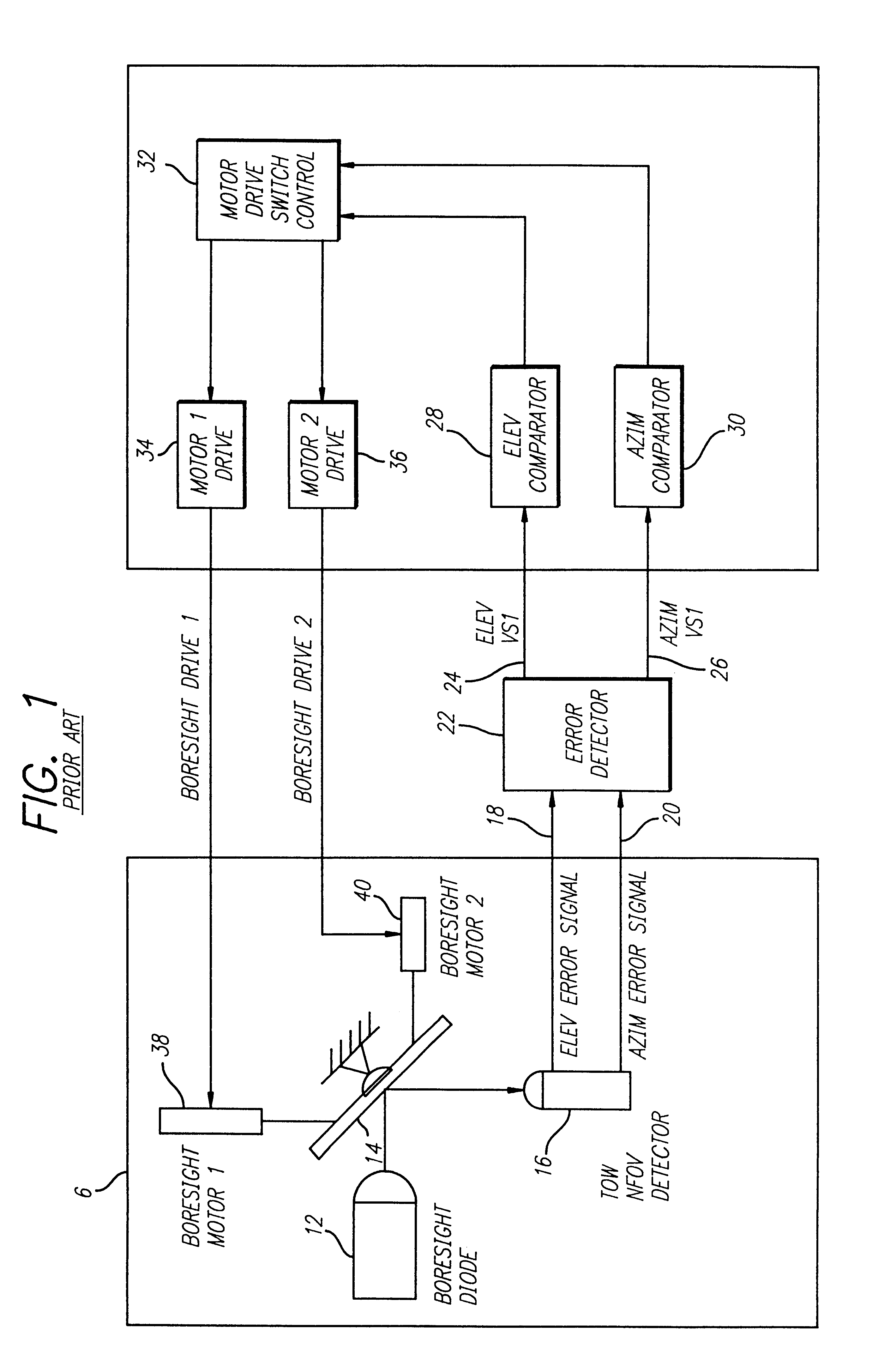
[0018]The following review of the operation of a traditional TOW missile firing electronics system is intended to facilitate an understanding of the present invention. Conventional TOW missile fire control systems have a boresigh...


PUM


Abstract

The need in the art is addressed by the improved missile fire control system of the present invention. In the illustrative embodiment, the inventive system is adapted for use with TOW missile systems and includes a telescope cluster assembly (10) for generating target position signals (18,20). A digital error detector (22′) receives and processes target position signals (18,20) from the telescope cluster assembly (10). The processed signals (24,26) are then fed to a stabilization control amplifier (50), where a microcontroller (56) steps through a set of instructions eliminate angular noise from the target position signals (24,26). The stabilization control amplifier (50) subsequently provides feedback to the telescope cluster assembly (10) for adjusting the line-of-sight in the telescope cluster assembly (10). Software instructions for the microcontroller (56) and constant reference data are stored in the microcontroller memory (not shown). An erasable programmable logic device (58) is used to output discreet signals for controlling mirror positioning. The inventive set of instructions includes sampling azimuth and elevation error signals (70); calculating the average of said azimuth and elevation error signals (72); performing a comparison of the average to a specified boresight limit (74); performing calculations on the averages in response to information received from the output of the comparison for determining motor runtimes (76,78,80,82,84); and repeating the above steps as necessary for obtaining azimuth and elevation signals within a specified limit.

Description

[0001]This invention was made with government support under Contract No. F0406-90-0004 awarded by the Department of the Air Force. The Government has certain rights in this invention.BACKGROUND OF THE INVENTION[0002]1. Field of Invention[0003]This invention relates to weapons fire control systems. Specifically, the present invention relates to systems for effecting boresight alignment for TOW (tube launched, optically tracked, wire-guided) missile fire control systems.[0004]2. Description of the Related Art[0005]The there is an ongoing need to increase the accuracy and performance of missile fire control systems. Efforts to obtain greater target percentages have led to the development of devices such as laser target designators. As targeting hardware becomes more sophisticated, the need increases for advanced electrical subsystems. This is particularly true of the TOW missile system. TOW missiles are relatively inexpensive, tube-launched, optically tracked wire-guided missiles. The ...

Claims


Application Information

Patent Timeline
IPC IPC(8): F41G7/32F41G7/20
CPCF41G7/32F41G7/001
Inventor SAND, RICHRAD J.WELLS, MICHAEL L.OLSON, MELVIN A.SUTTON, ERIC B.
Owner RAYTHEON CO
Why Eureka
Try Eureka