Attachment of bearing elements by deformation

a bearing element and deformation technology, applied in the direction of machines/engines, stators, liquid fuel engines, etc., can solve the problems of adhesive having to have time to cure, impeller damage, impeller bonding surface must be very clean,

Inactive Publication Date: 2005-05-31
BAKER HUGHES INC
View PDF19 Cites 16 Cited by
  • Summary
  • Abstract
  • Description
  • Claims
  • Application Information

AI Technical Summary

Benefits of technology

[0007]The bearing element for a centrifugal pump assembly is installed in a receptacle of a bearing holder, which may be a portion of an impeller or a portion of a di...

Problems solved by technology

One problem with adhesive is that the bonding surface of the impeller must be very clean and free of oil.
Also, the adhesive has to have time to cure.
Further, in high temperature wells, the temperature may exceed that of the adhesive, causing it to deteriorate.
If the thrust washer begins to spin relative to the impeller, damage to the impeller may occur.
Also, it may not be as reliable as the adhesive because variations in the force fit installation.
The differences in the coefficient of expansion of the impeller and a tungsten carbide thrust washer could cause the thrust washer to become loose at high temperatures.
An interferenc...

Method used


Image

  • Attachment of bearing elements by deformation
  • Attachment of bearing elements by deformation
  • Attachment of bearing elements by deformation

Examples


Embodiment Construction

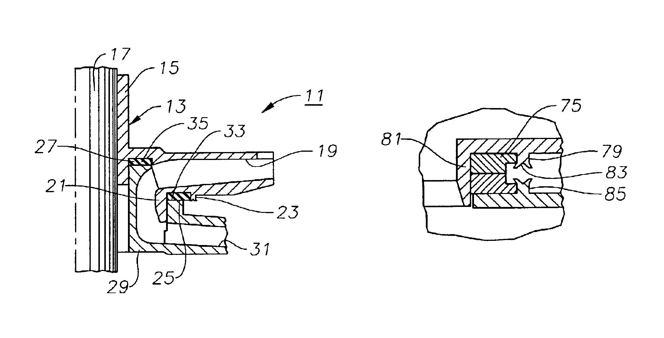
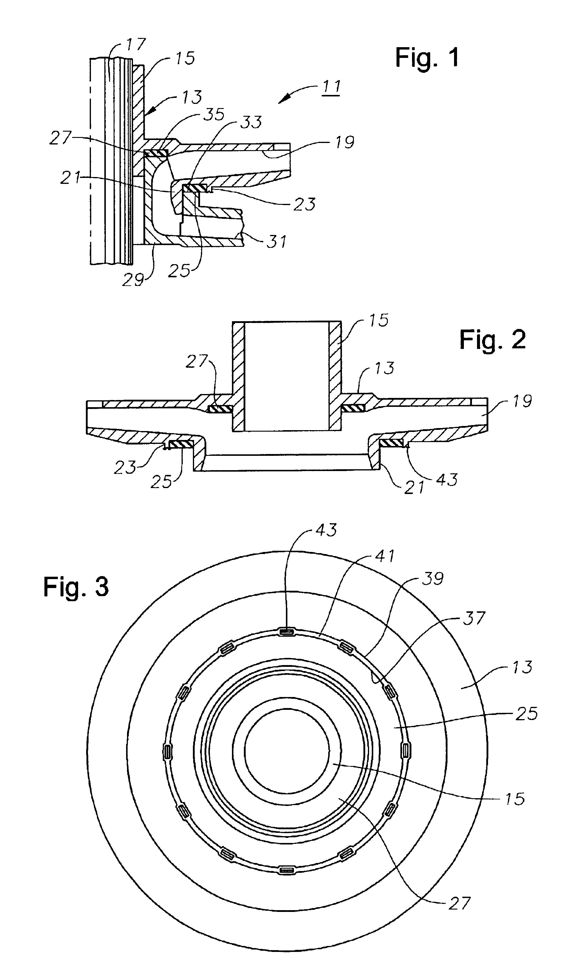
[0020]Referring to FIG. 1, pump stage 11 is part of a centrifugal pump stage of a pump that is particularly used for petroleum production. Normally, such a pump has a large number of pump stages 11, each having an impeller 13 that has a hub 15 mounted to a shaft 17 for rotation therewith. In most pumps, impeller 13 is free to move small distances in axial directions on shaft 17. Impeller 13 has a plurality of passages 19 that extend from an upstream inlet outward to the periphery of impeller 13. A skirt 21 surrounds the central inlet and depends downward or in upstream direction. A retaining wall 23 extends downward from the lower or upstream side of impeller 13 concentric with the axis and spaced radially outward from skirt 21.

[0021]Skirt 21 and retaining wall 23 define an annular receptacle for receiving an outer thrust washer 25. A second or inner thrust washer 27 may be located on impeller 13. Thrust washers 25, 27 are both secured in receptacles in a manner to cause them to rot...


PUM

PropertyMeasurementUnit
Diameteraaaaaaaaaa
Wear resistanceaaaaaaaaaa
Perimeteraaaaaaaaaa

Abstract

A method of installing an annular bearing element within a centrifugal pump utilizes a mechanical staking operation. The bearing element locates within a receptacle of a pump stage that is surrounded by a retaining wall. Once the bearing element is located within the retaining wall, the retaining wall is permanently deformed at various points against the bearing element. The bearing element, if of a hard wear resistant metal, may have flats for the circumferentially spaced apart deformations to locate within. The bearing element may be a thrust washer for transmitting downward thrust, or it may be a radial support bearing sleeve.

Description

FIELD OF THE INVENTION[0001]This invention relates in general to centrifugal pump stages, and in particular to a method of attaching radial and axial support bearing elements.BACKGROUND OF THE INVENTION[0002]Centrifugal pumps for petroleum production are made up of a large number of stages. Each stage has an impeller that is rotated by a shaft driven by an electrical motor. Each impeller is located within a stationary diffuser. Each diffuser has passages that extend downstream and radially inward toward the shaft for receiving fluid from an upstream impeller and delivering the fluid to a downstream impeller. Each impeller has a central inlet and passages that extend outward in a downstream direction for delivering well fluid to a downstream diffuser.[0003]The rotation of the impeller causes down thrust. Typically, each impeller is free to float axially on the shaft, and transmits the down thrust to its mating diffuser. Furthermore, thrust washers are located between the mating surfa...

Claims


Application Information

Patent Timeline
IPC IPC(8): F04D1/06F04D1/00F04D29/60F04D29/04F04D29/62F04D29/041
CPCF04D1/063F04D29/628F04D29/0413Y10T29/49318
Inventor GAY, FARRAL D.SHAFER, TERRY W.WILSON, B. LYLE
Owner BAKER HUGHES INC
Why Eureka
Try Eureka