Flexible microstrip signal and power bus cable

a microstrip and flexible technology, applied in the field of multi-layer cable systems, can solve the problem of reducing the level of electrical current that the cable can safely carry

Active Publication Date: 2005-05-31
SYAIR DESIGNS +1
View PDF20 Cites 19 Cited by
  • Summary
  • Abstract
  • Description
  • Claims
  • Application Information

AI Technical Summary

Benefits of technology

[0010]A flexible cable is described for use in distributing power and data bus communications throughout a control network. This flexible cable allows one connection to be made to service the entire control network, eliminating the need for interconnections between control nodes on the network.

Problems solved by technology

The employment of vias in prior art designs reduces the cross-sectional area of the conductive material (preferably copper) comprising the internal layers, which reduces the level of electrical current that the cable can safely carry.

Method used


Image

  • Flexible microstrip signal and power bus cable
  • Flexible microstrip signal and power bus cable
  • Flexible microstrip signal and power bus cable

Examples


Embodiment Construction

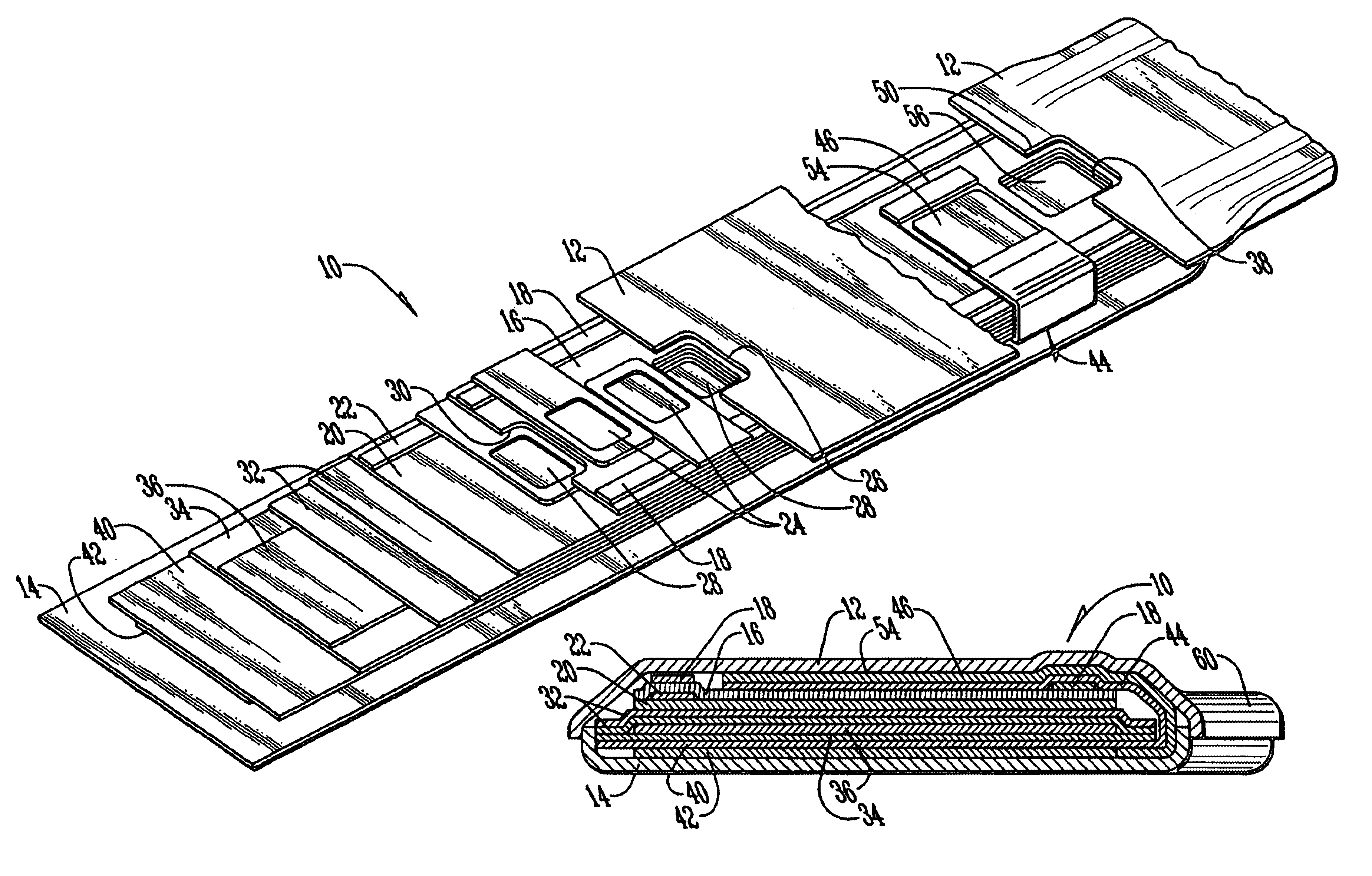
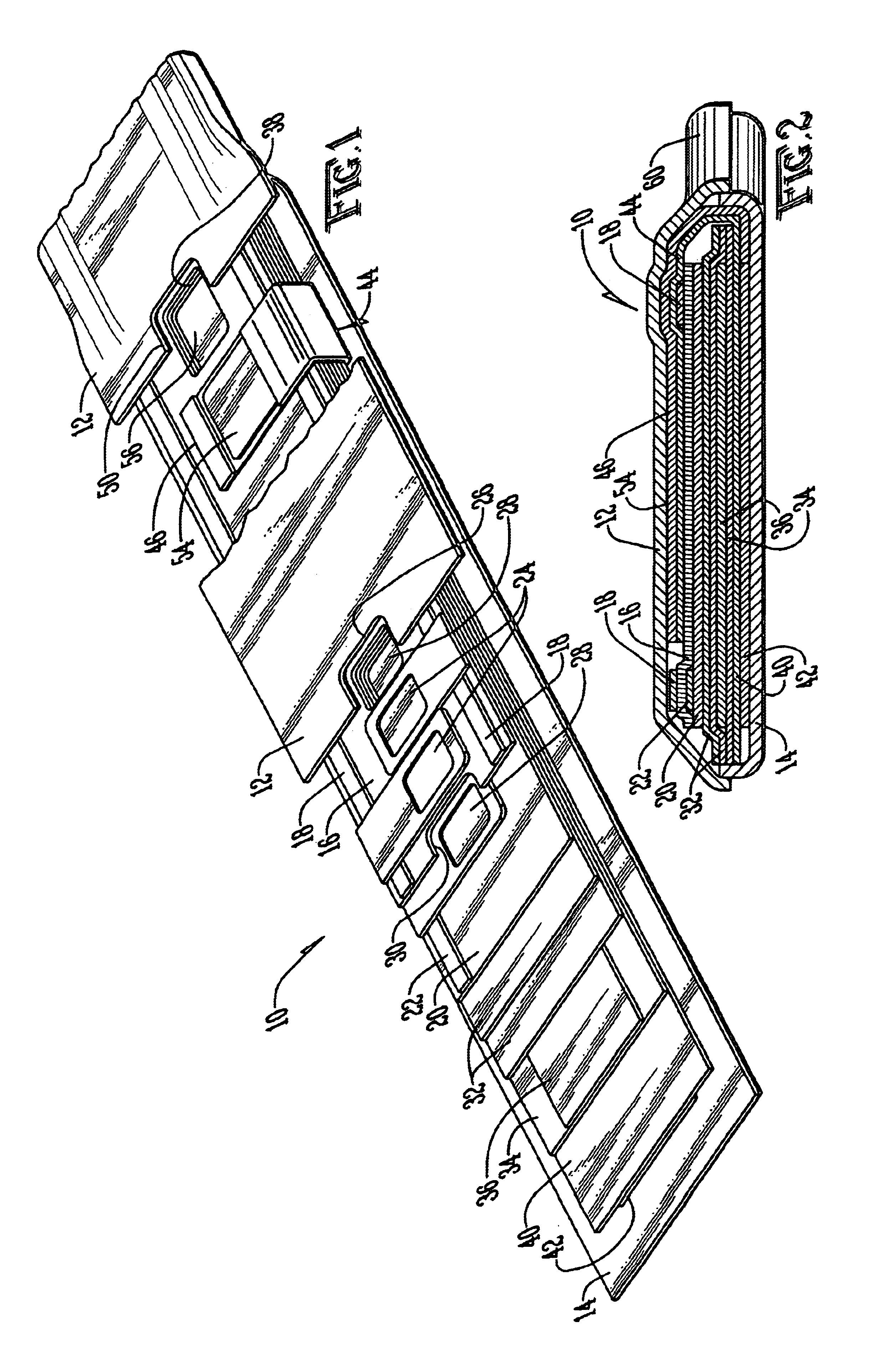
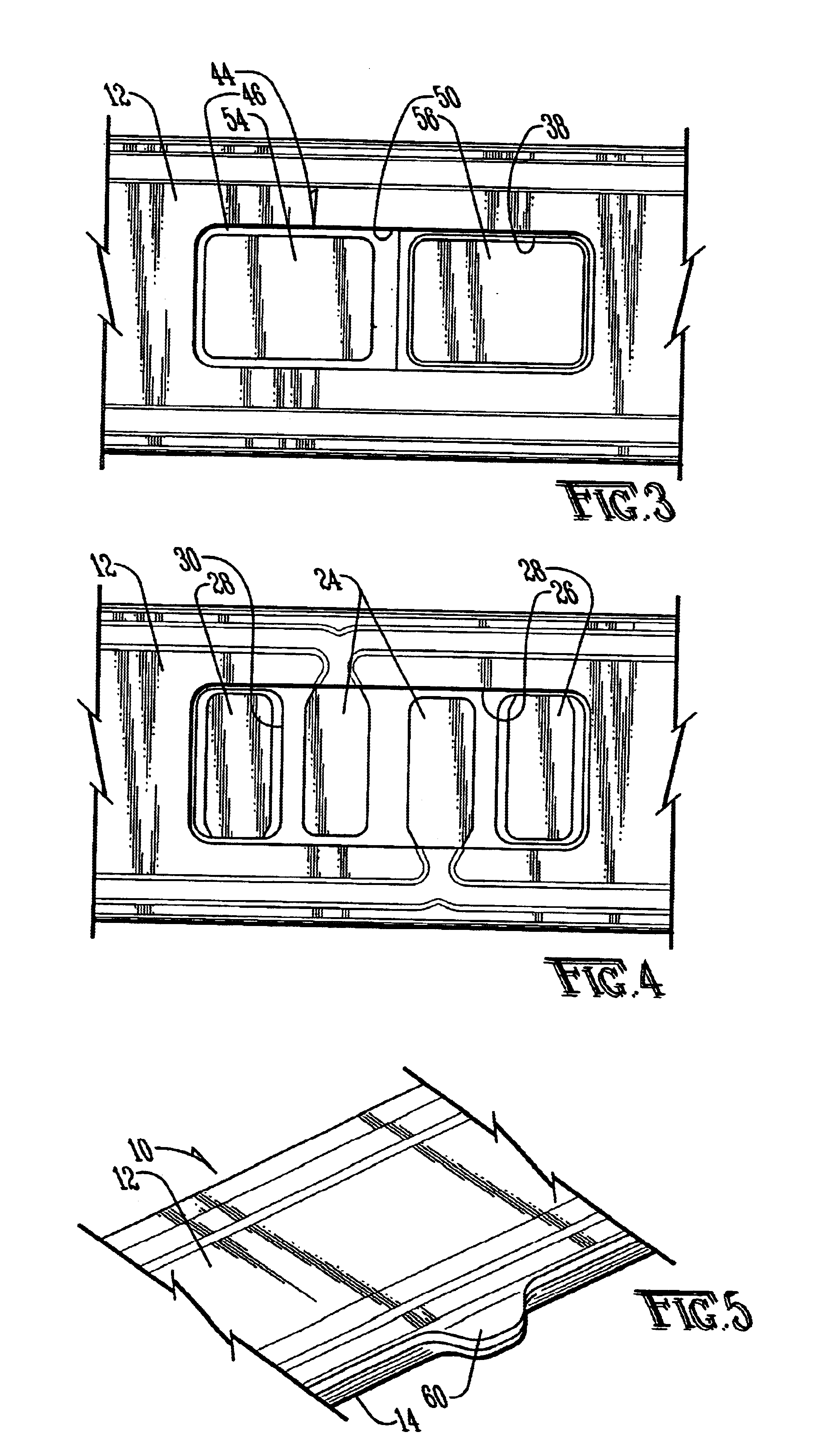
[0026]The preferred embodiment of the invention is a flexible, flat cable 10 for use in a network connecting components of an LED lighting system for installation in the cabin section of an aircraft or watercraft, as shown in FIG. 1. All necessary power and data bus communications connections to the control devices are supplied through cable 10. Cable 10 may be constructed using reel-to-reel flexible circuit processing techniques as are known in the art.

[0027]Cable 10 is protected on its upper and lower sides by top cover film 12 and bottom cover film 14, respectively. In the preferred embodiment, top cover film 12 is constructed of a 0.001 inch layer of polyimide film with a 0.001 inch layer of modified acrylic adhesive bonding applied to its lower surface. The polyimide film material with a suitable acrylic adhesive is available from Rogers Corporation of Chandler, Ariz. as part no. RFLEX2005C110. Bottom cover film 14 is constructed of a 0.002 inch layer of polyimide film with a 0...


PUM

PropertyMeasurementUnit
thickaaaaaaaaaa
thickaaaaaaaaaa
thickaaaaaaaaaa

Abstract

A multi-layered, flat, flexible cable capable of transmitting both power and multiple control signals to the components of a network is disclosed. The cable provides all connections on its top surface using a via-less design that does not reduce the cross-sectional area of power and ground buses within the cable. This effect is achieved through the use of folded conducting tabs appearing at periodic intervals along one of the power and ground conducting layers, which are folded over onto the top of the cable for electrical connection thereto.

Description

CROSS-REFERENCE TO RELATED APPLICATIONS[0001]The present application claims the benefit of U.S. provisional patent applications Ser. Nos. 60 / 455,269, entitled “Spectrally Calibratable Multi-Element RGB LED Light Source”; 60 / 455,129, entitled “Indirect Lighting System Architecture and Implementation”; 60 / 455,126, entitled “Anisotropic Etching of Silicon Wafer Materials to Create Micro-Reflector Cavities for LED Die”; and 60 / 455,127, entitled “Micro-Strip-Line Signal and Power Bus Flexible Cable and Method of Using Same,” each of which was filed on Mar. 17, 2003, and for each of which the inventor is Michael A. Halter. The present application is further related to the three co-pending applications filed on even date herewith entitled “Indirect Lighting System Architecture and Implementation,”“Anisotropic Etching of Silicon Wafer Materials to Create Micro-Reflector Cavities for LED Die”, and “Spectrally Calibratable Multi-Element RGB LED Light Source,” the inventor for each of which is...

Claims


Application Information

Patent Timeline
Patent Type & Authority Patents(United States)
IPC IPC(8): H01B7/08H01B9/00H01L25/075H05B33/02H05B33/08H05B44/00
CPCH01B7/0823H01B9/003H05B33/0842H05B33/0803H01L25/0753H01L2924/0002H05B45/00H01L2924/00
Inventor HALTER, MICHAEL A.
Owner SYAIR DESIGNS
Why Eureka
Try Eureka