Resistive superconducting current limiter

a current limiter and resistive technology, applied in resistor details, digital storage, instruments, etc., can solve problems such as worsening space utilization, and achieve the effect of reducing current density peaks

Inactive Publication Date: 2005-05-31
ABB RES LTD
View PDF8 Cites 1 Cited by
  • Summary
  • Abstract
  • Description
  • Claims
  • Application Information

AI Technical Summary

Benefits of technology

[0005]The object of the present invention is to reduce current density peaks in a corner element between two straight conductor track sections in a resistive superconducting current limiter, when limiting occurs.
[0008]According to a first embodiment, the conductor assembly is removed in the intersection region on the inner edge of the canonic connection, thus enlarging the effective mean radius of the corner element in comparison to that of the canonic connection. If the conductor assembly is constructed in the form of layers, this advantageously increases the thickness of the superconducting layer since, otherwise, a reduction in the rated current level IN is unavoidable without reductions in the space utilization.
[0009]According to a further embodiment, in contrast, the superconducting layer is not changed in the intersection region, and the modification of the conductor cross section according to the invention is carried out only via the bypass. This avoids cracks being produced in the high-temperature superconductor as a result of any mechanical processing following the formation of the superconducting layer.
[0010]A centroid, with average conductivity, of the modified conductor cross section is preferably in this case located closer to the outer edge of the canonic connection, so that, once again, the effective mean radius of the corner element is enlarged, and the fault current is thus subjected to a less abrupt direction change. The centroid with average conductivity is influenced, for example, by thinning or entirely removing the bypass in the region of the inner edge. It is also possible to increase the thickness of the bypass along the outer edge, by constructing a further bypass layer. A further alternative, without influencing the geometric centroid, is based on alloying impurities to the bypass in the area of the inner edge, as a result of which its electrical resistance there is increased.

Problems solved by technology

However, at the same time, this makes the space utilization worse, that is to say the percentage of the mount body surface which is covered by the conductor track structure since, if the conductor track width is constant, the straight sections must be separated from one another by a specific minimum lateral separation at the turning points between successive, approximately parallel, straight sections.

Method used


Image

  • Resistive superconducting current limiter
  • Resistive superconducting current limiter

Examples


Embodiment Construction

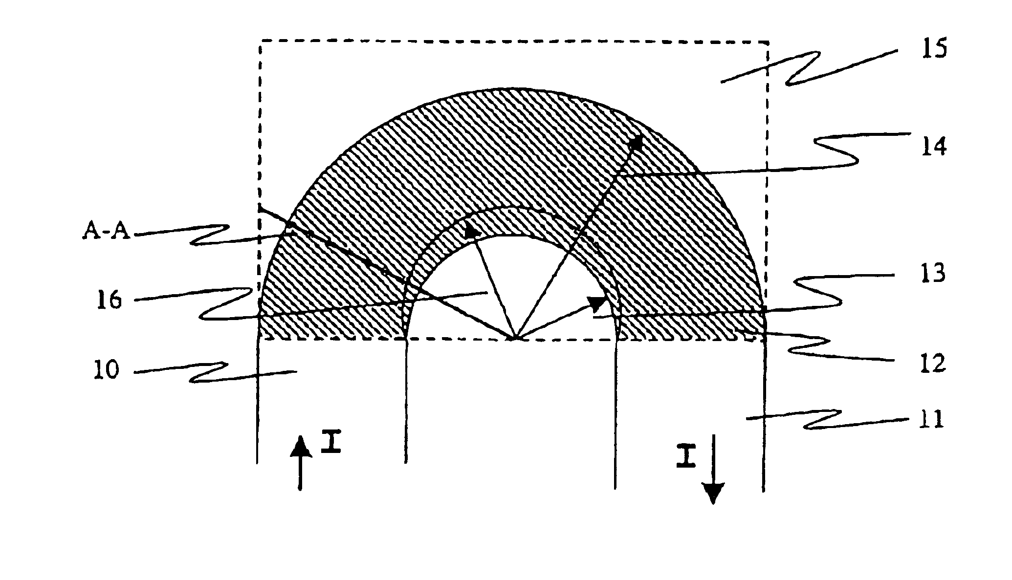
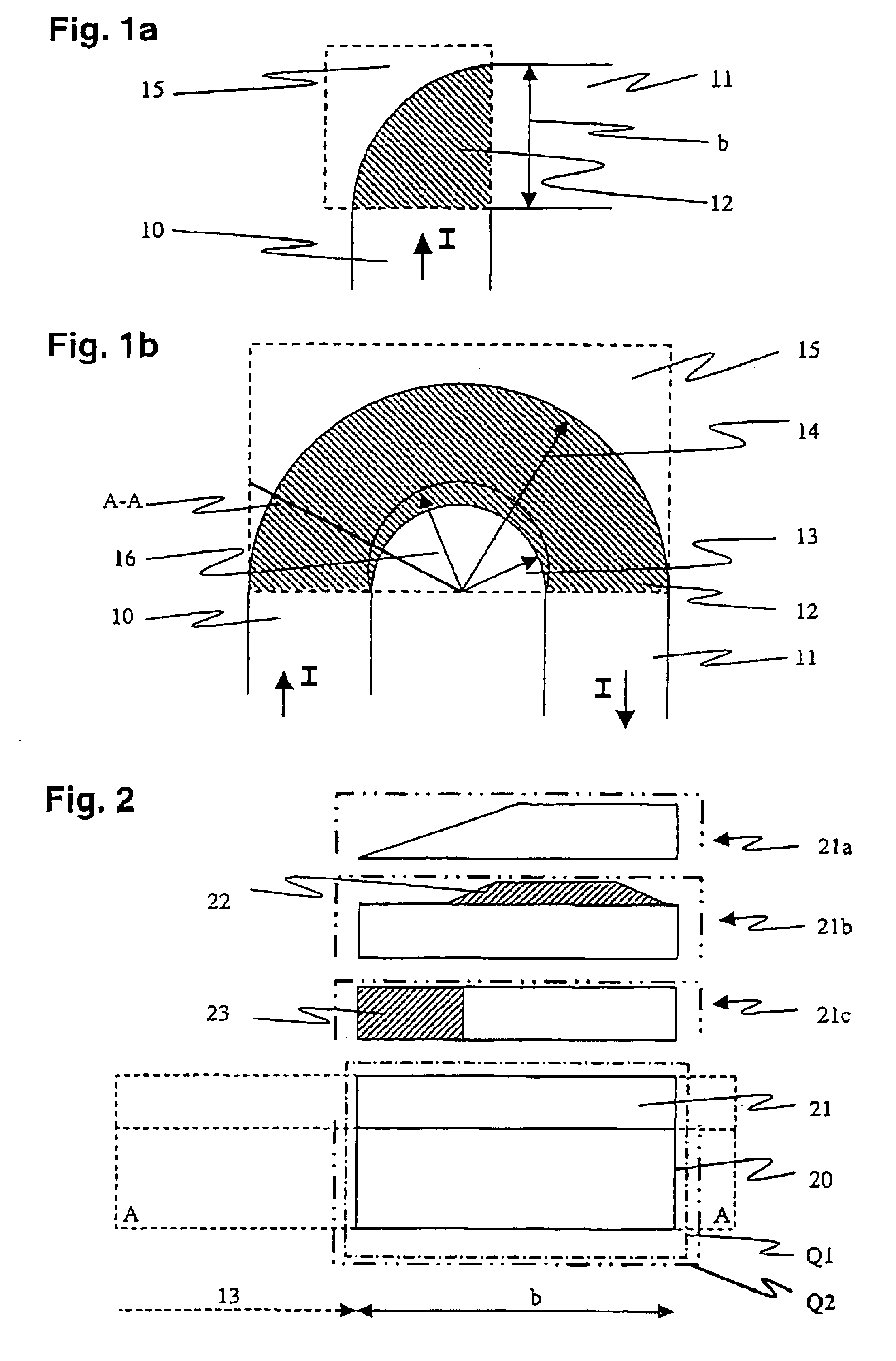
[0016]Resistive current limiters based on high-temperature superconductors are preferably produced in the form of flat modules with an electrically insulating mount or substrate, and conductor tracks applied on both sides of it. The latter comprise a conductor assembly formed from a high-temperature superconductor and a metallic electrical bypass composed of silver and / or steel. During rated operation, a rated current IN flows through the superconductor. When limiting occurs, that is to say when the rated current has risen above the critical current IC of the superconductor and a voltage drop occurs in the superconductor, the bypass carries the majority of the fault current, thus reducing the load on the superconductor. The following analyses are based on the assumption that the superconductor forms a first layer, and that the bypass forms a second layer, applied to the superconductor.

[0017]In general, the conductor tracks are in the form of progressive or rectangular spiral meander...


PUM


Abstract

The present invention relates to a resistive superconducting current limiter with a meandering shape. This current limiter avoids current density peaks at the turning points (12) or corners of the conductor track (10, 11) in that the central path of the fault current when limiting occurs is artificially increased by appropriate design of the turning points. For this purpose, conductor material is removed in the region of the inner edge of the turning points (13), or the electrical bypass is reinforced at its outer edge (14).

Description

FIELD OF THE INVENTION[0001]The present invention relates to the field of applied high-temperature superconduction. It relates in particular to a resistive superconducting current limiter as claimed in the precharacterizing clause of patent claim 1.BACKGROUND OF THE INVENTION[0002]High-temperature superconductors are used, by way of example, in superconducting short-circuit current limiters for electrical distribution and transmission networks. A current limiter such as this makes use of the fact that a superconductor retains its superconductivity at an appropriately low operating temperature only for as long as the current density of a current flowing through it remains below a specific limit value, which is referred to as the critical current density. If a short circuit occurs in the corresponding power supply network, the current in the current limiter rises to a fault current which is greater than the critical value. This results in the superconductor changing to the resistive s...

Claims


Application Information

Patent Timeline
Patent Type & Authority Patents(United States)
IPC IPC(8): H01L39/16
CPCH01L39/16H10N60/30
Inventor CHEN, MAKANPAUL, WILLILAKNER, MARTINRHYNER, JAKOB
Owner ABB RES LTD
Why Eureka
Try Eureka