
Modular lighting device and actuation system

a lighting device and module technology, applied in the field of modular lighting devices and actuation systems, can solve the problems of inability to meet the needs of users, inability to control the lighting, so as to achieve efficient power management

Inactive Publication Date: 2005-05-31
ACOLYTE SYST +1
View PDF6 Cites 60 Cited by
  • Summary
  • Abstract
  • Description
  • Claims
  • Application Information

AI Technical Summary

Benefits of technology

"The lighting device described in this patent uses a programmable chip, a push button switch, a printed circuit board, a capacitor, a battery holder, a battery, a multidirectional light, jumpers, a diode, and a resistor. The chip is programmed with a set of logic that allows it to respond to various stimuli, such as magnetic fields, sound, light, or radio waves. The device determines the appropriate levels and periods of illumination based on the stimulus. The device is designed to use minimal power and has a power-saving feature that allows it to maintain illumination for a specific period of time while reducing power to a negligible level."

Problems solved by technology

An assembly in accordance with the state of the art is prone to premature battery drain.
Such systems use wires, which can fray, require added solder points, are susceptible to corrosion, are difficult to handle and time consuming to install.
This can cause vagaries and inaccuracies.
Also, devices using floating point arithmetic logic when fixed point logic would suffice are less efficient, requiring more logic steps, greater power and are prone to problems.

Method used


Image

  • Modular lighting device and actuation system
  • Modular lighting device and actuation system
  • Modular lighting device and actuation system

Examples


example

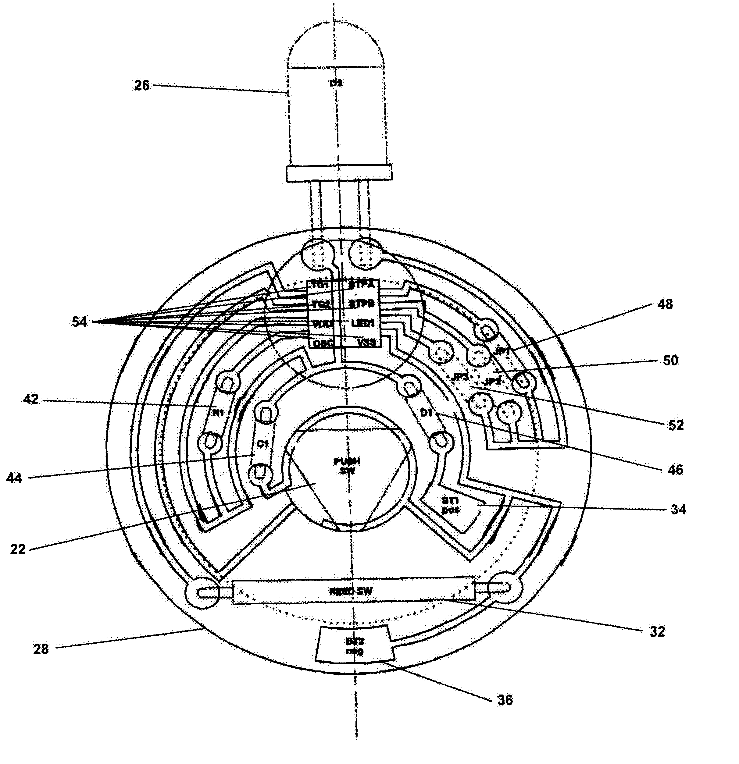
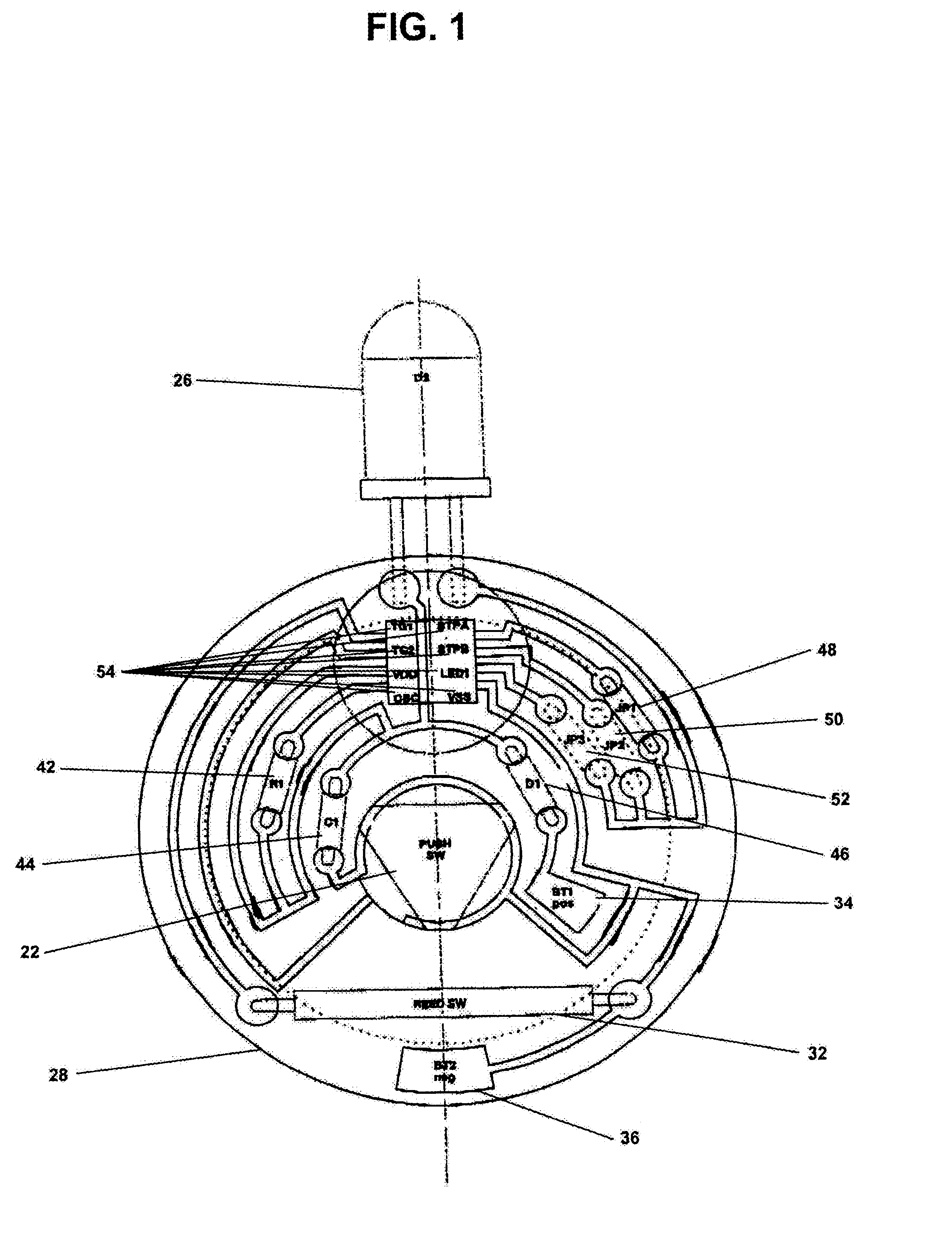
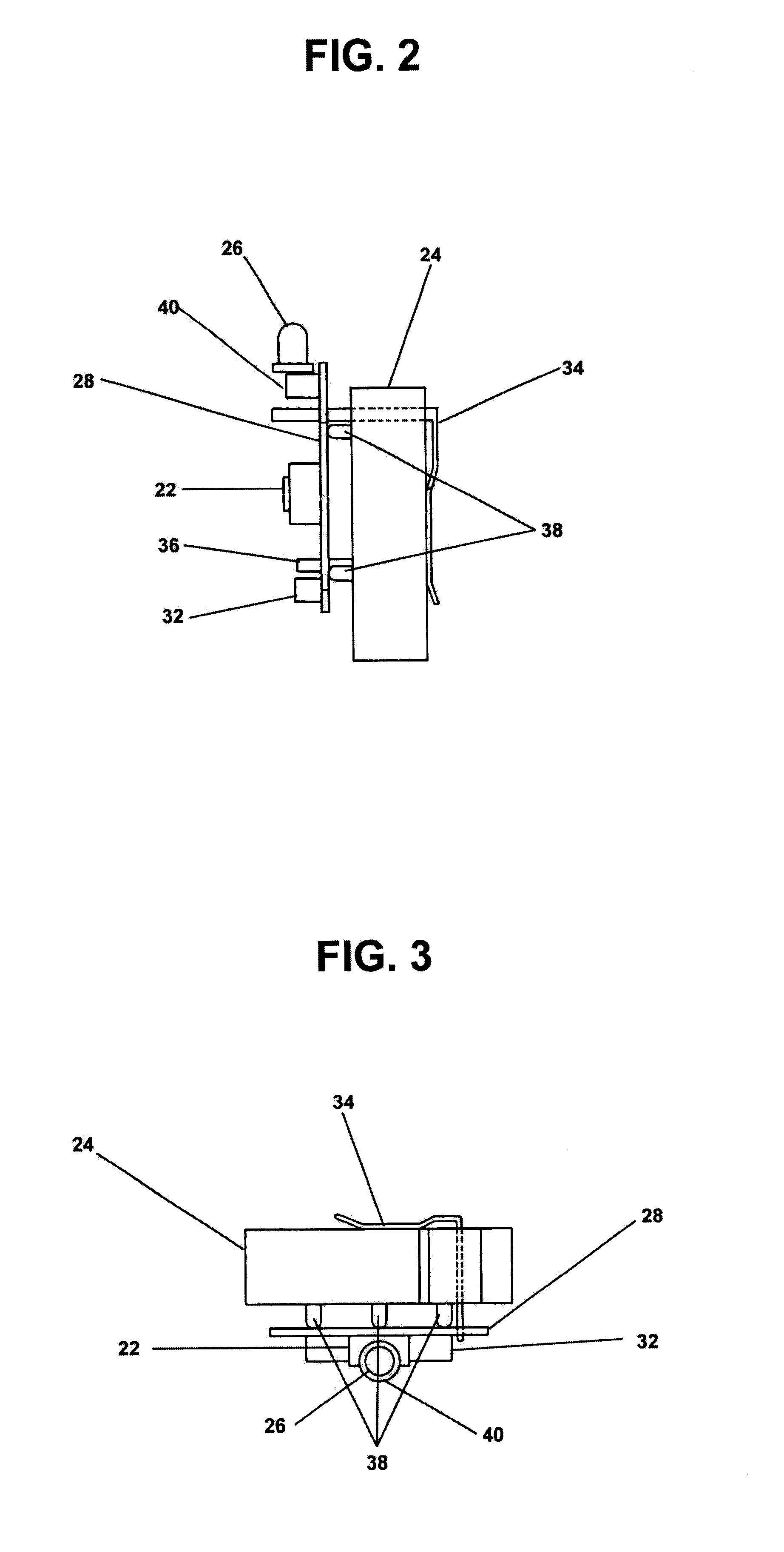
Set out below is a preferred series of parts for the device:

[0062]1. A printed Circuit Board.[0063]2. ADPCM voice synthesizer type W528S03 speech chip.[0064]3. A 0.01 μfd capacitor.[0065]4. Meder Reed Switch Part. No. MK15-B-2.[0066]5. MPD Battery Holder BH 1000-G-ND.[0067]6. CR-3032 Battery.[0068]7. E-switch Push Button TL3301N26OQG.[0069]8. 3 mm multidirectional light commercially produced by Hiyoshi Electric Co., Ltd.[0070]9. 3 jumpers.[0071]10. A low power diode IN914.[0072]11. A 1.2 Meg Ohms resistor which establishes 3 Mhz clock speed on speech chip.


PUM


Abstract

An illumination device that is highly durable, wireless, programmable, inexpensive emits little to no heat, is shockproof, water-resistant, energy efficient, is multidirectional, responds to a multitude of stimulus and adapts for a multitude of purposes. The programmable device provides varying amounts of light in accordance with programmed instructions.

Description

FIELD OF THE INVENTION[0001]The instant invention relates generally to lighting devices and more specifically to a small, modular, digital, solid-state lighting device and actuation systems.BACKGROUND OF THE INVENTION[0002]Since the age of candles and oil lamps numerous advances have been made in the area of portable illumination devices. By the late 19th century, flashlights utilizing simple circuitry represented the next generation of illumination devices. Since the invention of flashlights, they have generally utilized a filament light bulb, an on / off switch and battery connected in an operative series. Such flashlights are generally well known within the art and for almost a century flashlight technology has generally remained unchanged.[0003]There are a number of flashlights on the market that are well known in the art. Included in these are two AAA-cell powered Lights (Pen Light and Mini-Pocket Light), the MiniMityLite, Mitylite, the photon light and Super Mitylite. While thes...

Claims


Application Information

Patent Timeline
Patent Type & Authority Patents(United States)
IPC IPC(8): H05B37/02
CPCH05B37/0209H05B47/17H05B47/165
Inventor GUERRIERI, SALVATOREADELMAN, LAWRENCE DAVID
Owner ACOLYTE SYST
Learn More