
Optical path structure for open path emissions sensing with particulate matter and lubricating oil consumption absorption methodology

a technology of optical path structure and open path, which is applied in the direction of optical radiation measurement, structural/machine measurement, instruments, etc., can solve the problems of inability to measure particulate matter (pm) in current open path embodiments, respiratory or heart problems, and the need for radiation sources and detectors to be placed on opposite sides

Inactive Publication Date: 2005-05-31
SPX CORP
View PDF73 Cites 11 Cited by
  • Summary
  • Abstract
  • Description
  • Claims
  • Application Information

AI Technical Summary

Benefits of technology

[0014]It is therefore a feature and advantage of the present invention to provide an improved optical transmission, reflection and detection system. In accordance with one embodiment of the present invention, a device for measuring particulate matter includes a light source that emits light, a receiver positioned to receive light emitted from the light source, and a detection unit in communication with the receiver. The detection unit detects an amount of particulate matter based upon the light received by the receiver.
[0015]In an alternate embodiment, a method for determining a concentration of particulate matter includes the steps of emitting light from a light source, receiving the light emitted from the light source in a receiver, and determining an amount of particulate matter using the light received in the receiver.
[0016]In accordance with another embodiment, a system for measuring particulate matter includes a light source means for emitting light and a receiver means for receiving the light emitted from the light source means. The receiver means is positioned to receive the light emitted from the light source means. The system further includes a detection unit means for determining an amount of particulate matter based upon the light received by the receiver. The detection unit means is in communication with the receiver means.
[0017]There have thus been outlined, rather broadly, the more important features of the invention in order that the detailed description thereof that follows may be better understood, and in order that the present contribution to the art may be better appreciated. There are, of course, additional features of the invention that will be described below and which will form the subject matter of the claims appended hereto.
[0018]In this respect, before explaining at least one embodiment of the invention in detail, it is to be understood that the invention is not limited in its application to the details of construction and to the arrangements of the components set forth in the following description or illustrated in the drawings. The invention is capable of other embodiments and of being practiced and carried out in various ways. Also, it is to be understood that the phraseology and terminology employed herein, as well as the abstract, are for the purpose of description and should not be regarded as limiting.

Problems solved by technology

A disadvantage of many known arrangements is that the radiation sources and detectors must be placed on opposite sides of the roadway from each other.
Furthermore, current open path embodiments are unable to measure particulate matter (PM), as they are equipped to only measure the density, referred to as “opacity”, of smoke emanating from a vehicle's exhaust.
Particles less than 1 micron in diameter tend to lodge deep within the lungs, where the fine particles can cause respiratory or heart problems.
PM2.5 also impairs visibility.
A measurement of opacity historically has not correlated well with actual PM measurements, nor have opacity measurements properly characterized the particle sizes that most affect human health and welfare.
Nonetheless, the TEOM methodology requires a vehicle to be taken to a specific testing facility, due to the closed-path nature of its methodology, and requires special plumbing modifications if particulates are to be speciated from filter media.
The particulate matter tends to accumulate on the inside of the hose leading from the vehicle tailpipe to the dilution tunnel, causing very small particles to be released during subsequent tests.
Furthermore, current open path sampling art for measuring opacity does not have a good correlation with the Society of Automotive Engineers (SAE) Snap-Acceleration Smoke Test Procedure issued in SAE bulletin J1667.
Also, current open path emissions sampling art cannot determine if a tested vehicle was burning excessive amounts of lubricating oil from its engine, due to wear of internal sealing components within the engine or other reason.

Method used


Image

  • Optical path structure for open path emissions sensing with particulate matter and lubricating oil consumption absorption methodology
  • Optical path structure for open path emissions sensing with particulate matter and lubricating oil consumption absorption methodology
  • Optical path structure for open path emissions sensing with particulate matter and lubricating oil consumption absorption methodology

Examples


Embodiment Construction

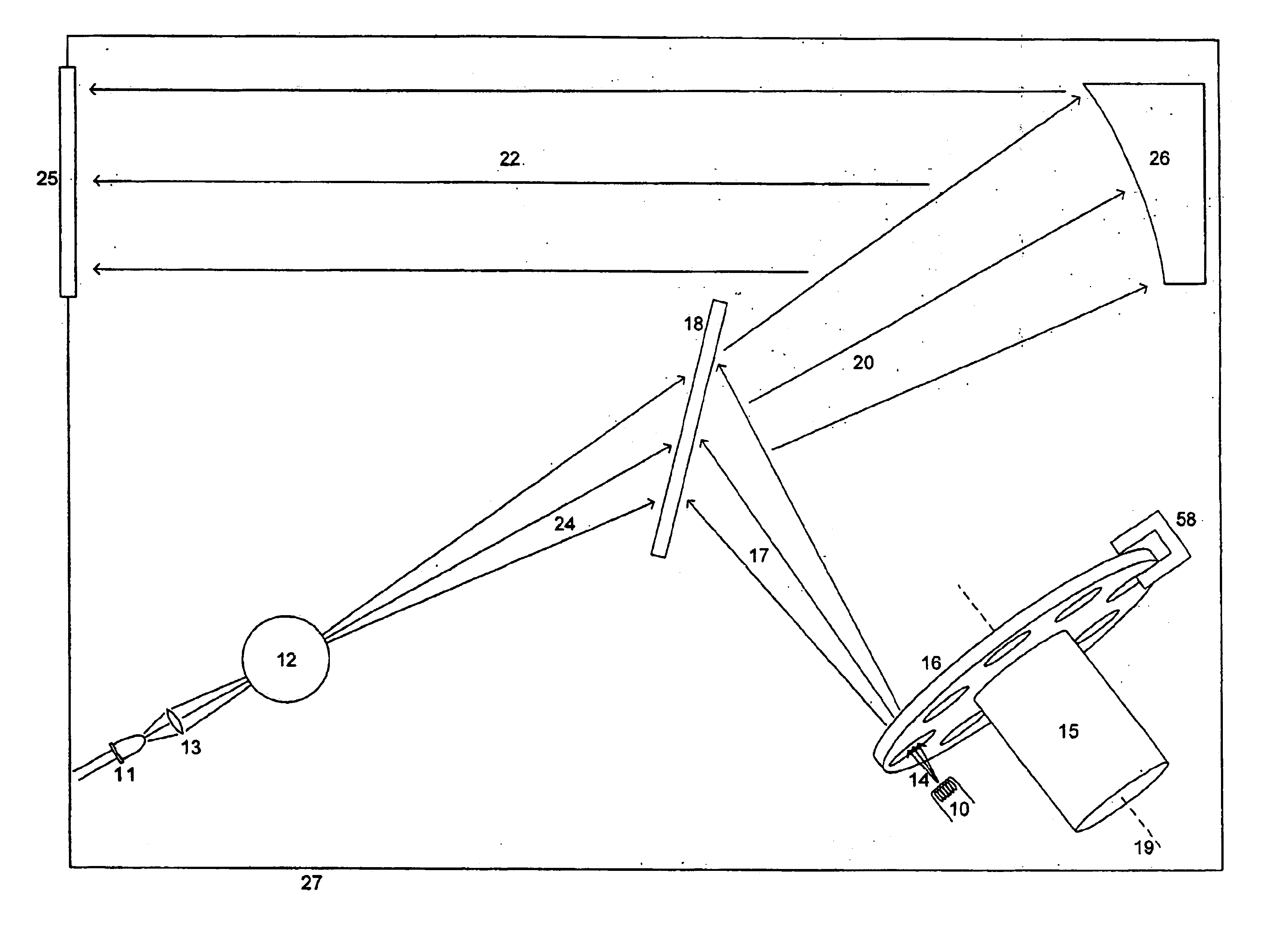
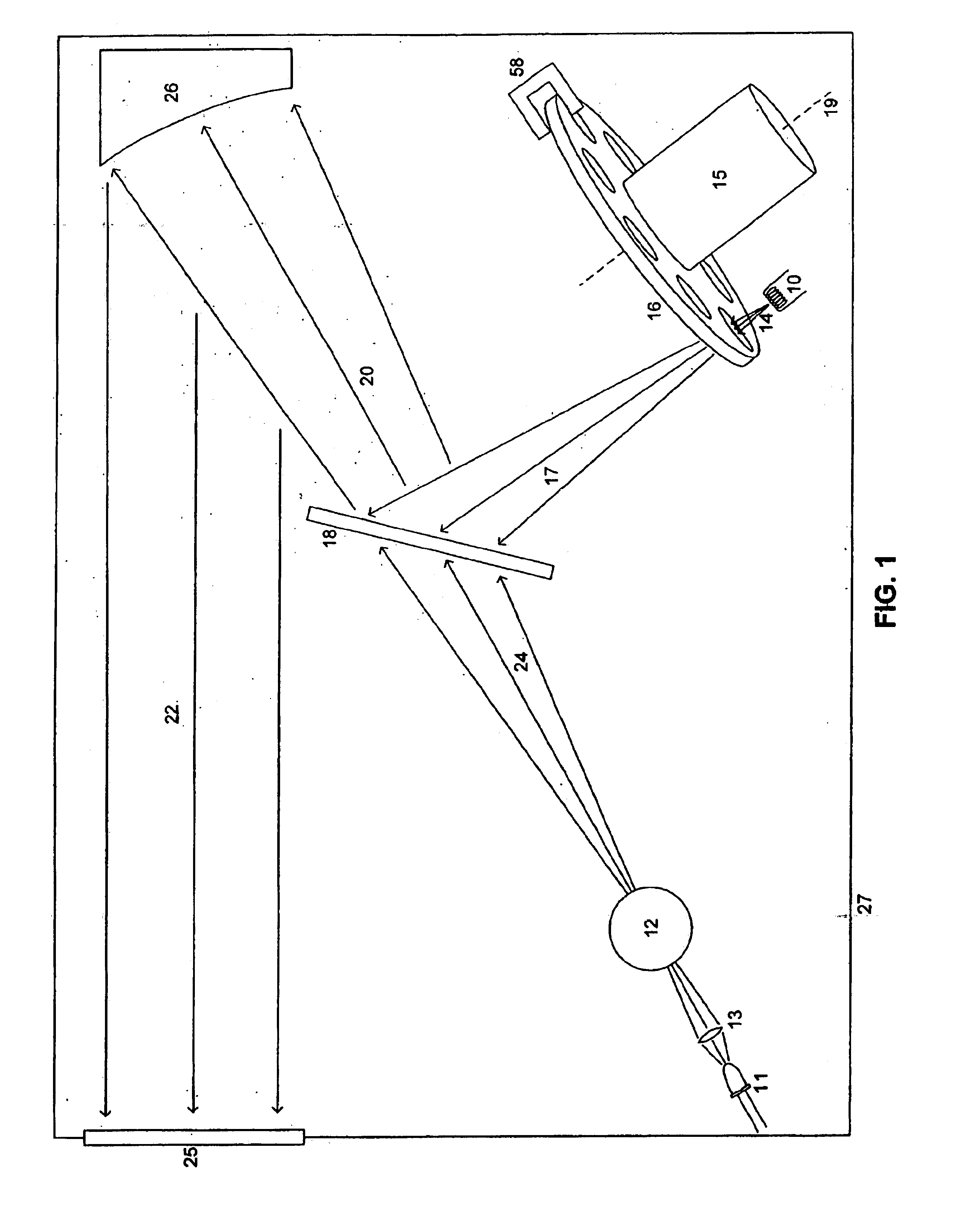
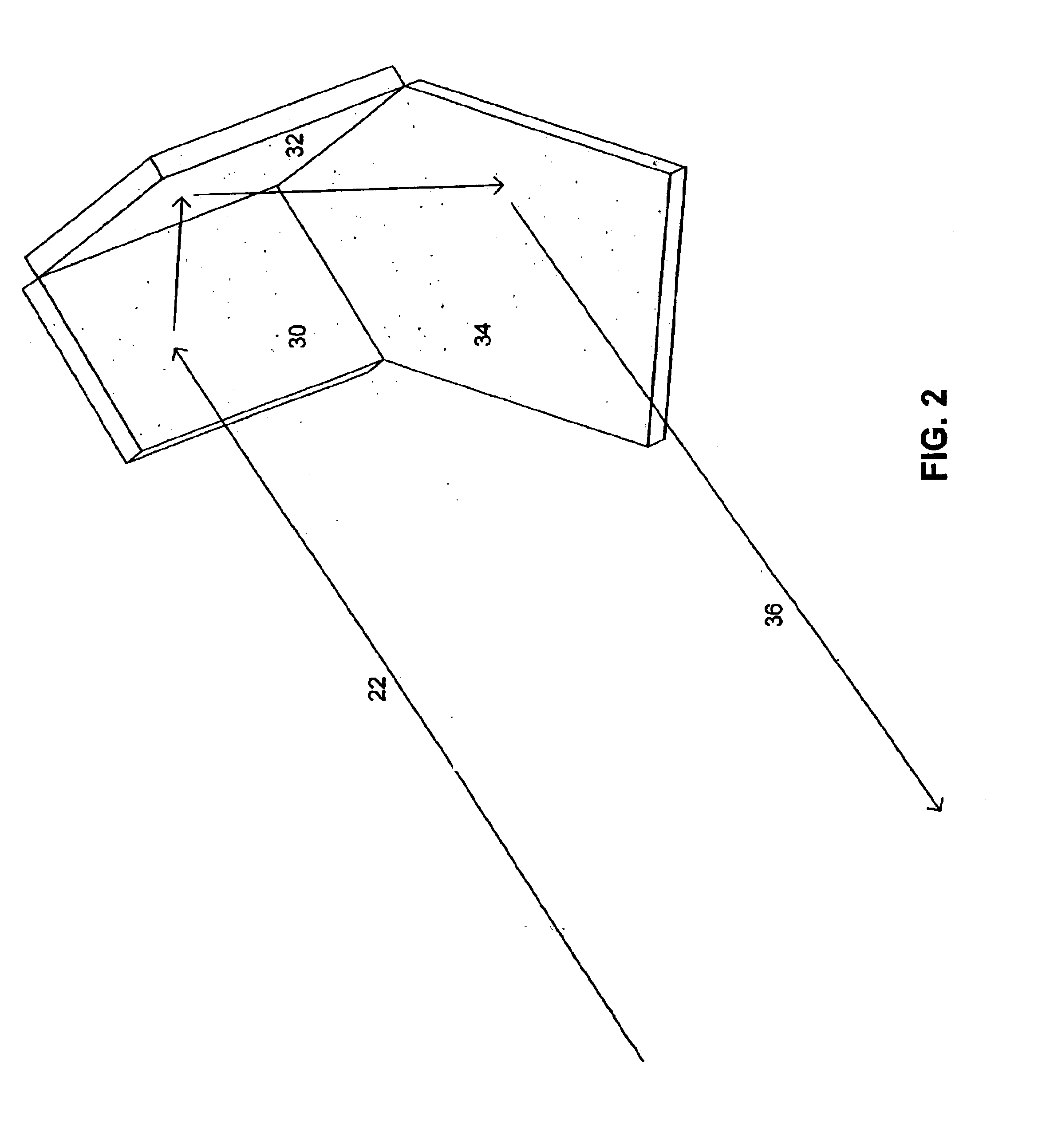
[0034]A preferred embodiment of the present invention provides an improved optical source, reflection, and detection system for gas component analysis. A preferred embodiment includes a light source unit, which preferably includes one or more of infrared, visible, and ultraviolet light sources; a reflection unit; and a light detection unit. Preferably, light sources and detectors are contained within a housing. The light is transmitted through a gas, such as air containing vehicle emissions, reflected, and detected for analysis and measurement of the amount of absorption that has occurred at known wavelengths of the light. The amount of absorption may be used to determine concentrations of gases corresponding to the specific wavelengths.

[0035]In a preferred embodiment of this invention, infrared, visible, and ultraviolet radiation is combined into one beam, directed across a path such as a road along which vehicles travel and generate exhaust, reflected back across the path, collect...


PUM


Abstract

A device for measuring particulate matter includes a light source that emits light, a receiver positioned to receive light emitted from the light source, and a detection unit in communication with the receiver. The detection unit detects an amount of particulate matter based upon the light received by the receiver.

Description

PRIORITY[0001]The present application is a continuation-in-part of U.S. patent application Ser. No. 09 / 934,272, filed Aug. 21, 2001 now U.S. Pat. No. 6,744,516, entitled Optical Path Structure for Open Emissions Sensing, the disclosure of which is incorporated herein by reference in its entirety.FIELD OF THE INVENTION[0002]The present invention relates generally to remote sensing systems. More particularly, the present invention relates to an apparatus for transmitting, reflecting, and detecting light in an open path sensing system such as a vehicle emission sensing system, having use in detecting and / or measuring one or more components of the air through which the light passes.BACKGROUND OF THE INVENTION[0003]Current methods of determining whether a vehicle is compliant with emission standards include open path and closed path emissions measurement systems. In a closed path system, an emission sensor is directly connected to the exhaust of the vehicle, such as by insertion into a t...

Claims


Application Information

Patent Timeline
IPC IPC(8): G01M15/04G01M15/10G01N21/53G01N21/47G01N21/31G01N21/33G01N21/35G01N1/22
CPCG01M15/108G01N21/33G01N21/3504G01N21/534G01N1/2252G01N2021/3527G01N2001/2264G01N2021/3155G01N2021/3174G01N2021/3513
Inventor FOLEY, THERESA A.DIDOMENICO, JOHNGENTALA, ROBERT A.RENDAHL, CRAIG S.
Owner SPX CORP
Learn More