Image recording device

a recording device and image technology, applied in the direction of digital output to print units, instruments, printers, etc., can solve the problems of inability to obtain the amount of light required, low luminous efficiency, white lamps, etc., to prevent crosstalk generation, small and inexpensive

Inactive Publication Date: 2005-05-31
FUJIFILM HLDG CORP +1
View PDF3 Cites 69 Cited by
  • Summary
  • Abstract
  • Description
  • Claims
  • Application Information

AI Technical Summary

Benefits of technology

[0007]In view of the conventional problems described above, an object of the present invention is to provide an image recording device which is small and inexpensive, prevents generation of crosstalk, and with which high-quality images can be obtained at high speed.

Problems solved by technology

However, in the image recording device in which a white lamp is used as the light source and the light shutter array is used as an external modulation element, the following problems arise: (1) white lamps have low luminous efficiency and cannot obtain the amount of light required to expose color photosensitive materials; (2) due to short life span, white lamps need to be frequently replaced and are therefore inconvenient; and (3) when a white lamp is used, color separation needs to be carried out by using a color wheel or the like having filters of R, G, and B, and since a rotating mechanism for mechanically rotating the color wheel is necessary, the device becomes large, and it takes time to switch the filters.
However, since the organic EL elements form a diffusion light source, a problem arises in that direct modulation of the organic EL elements results in optical crosstalk.

Method used


Image

  • Image recording device
  • Image recording device
  • Image recording device

Examples


first embodiment

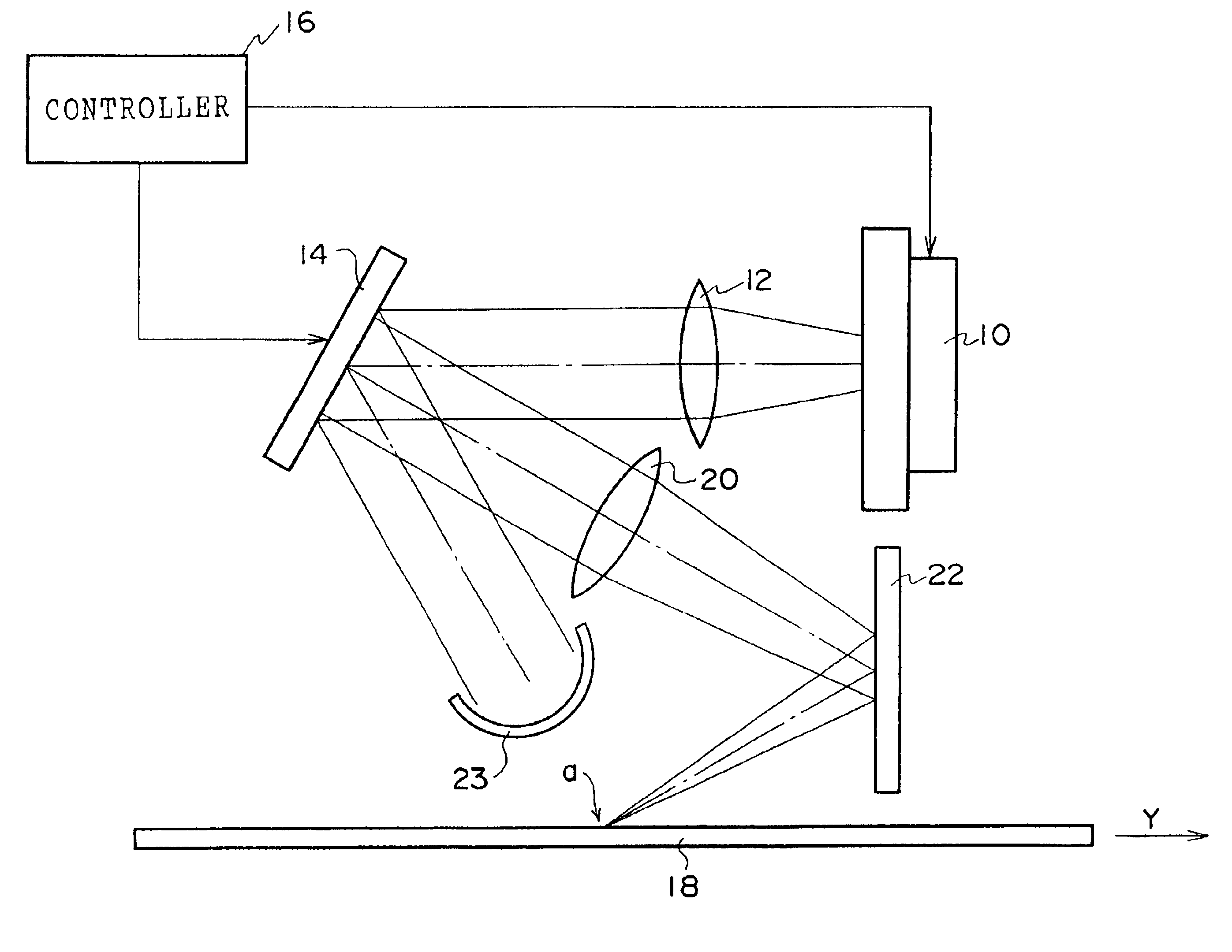
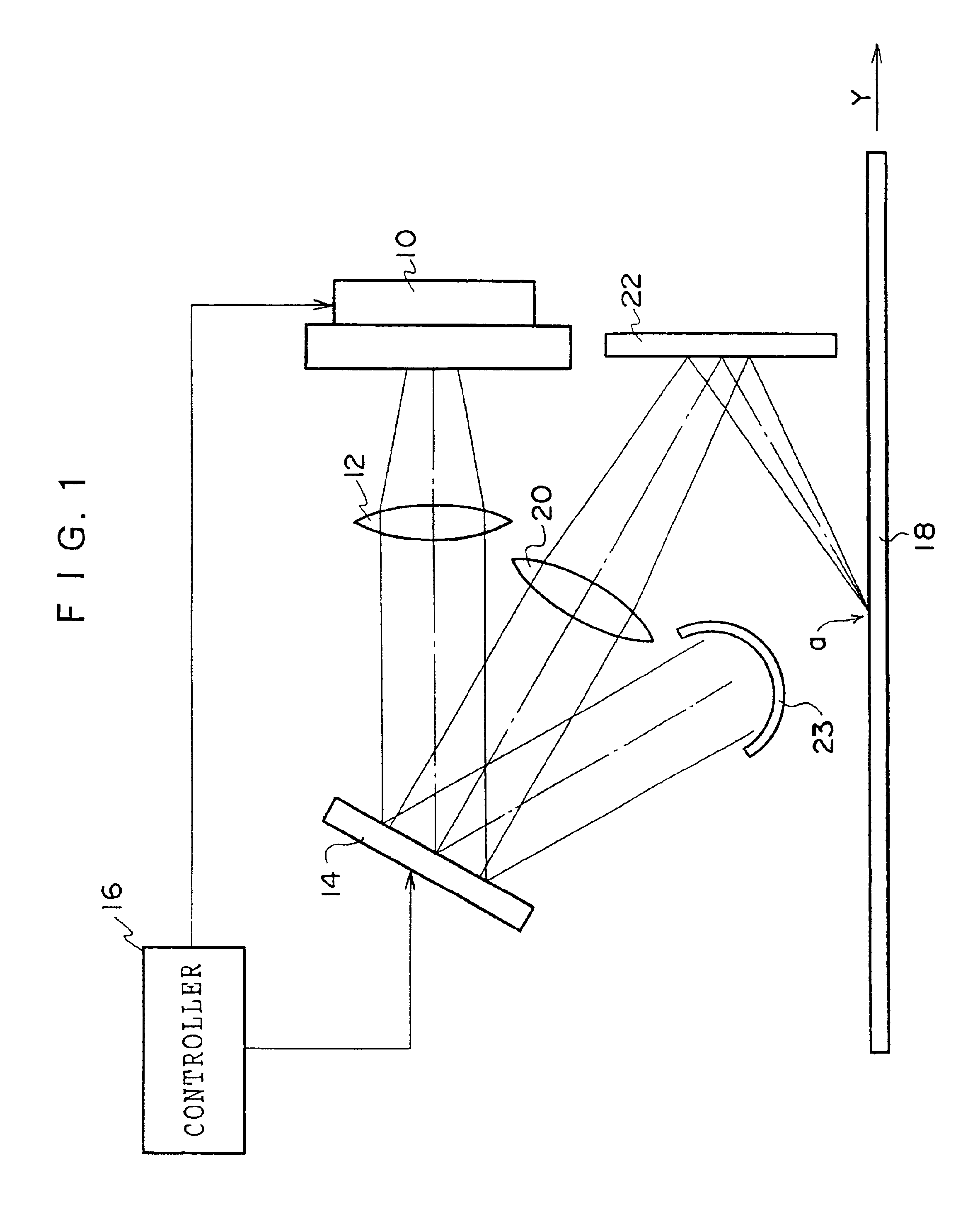
[0025]FIG. 1 shows the schematic structure of an image recording device according to a first embodiment of the present invention. As shown in FIG. 1, the image recording device includes a light source 10 formed by organic electroluminescence elements (hereinafter referred to as “organic EL elements”). A collimator lens 12 which collimates light beams emitted from the light source 10 is disposed at the light-exiting side of the light source 10, and a reflection type light modulator (referred to as a “DMD”, i.e., Digital Micromirror Device) 14 is disposed at the light-exiting side of the collimator lens 12. The light source 10 and the DMD 14 are connected to a controller 16.

[0026]On the optical axes of the light beams reflected by micromirrors of the DMD 14 when they are on (which will be described later), a condenser lens 20 and a reflecting mirror 22 are disposed so as to focus the light beams reflected by the DMD 14 onto a recording surface of a color photosensitive material 18. Fu...

second embodiment

[0039]Hereinafter, a second embodiment of the image recording device of the present invention will be described. The second embodiment is an example in which organic EL arrays, in which the organic EL elements of R, G, and B are linearly arranged respectively, are used as the light source, and external modulation is carried out by using a DMD structured by linearly arranging the micromirrors. Since the present second embodiment is substantially the same as the first embodiment, only the point different from the first embodiment will be described.

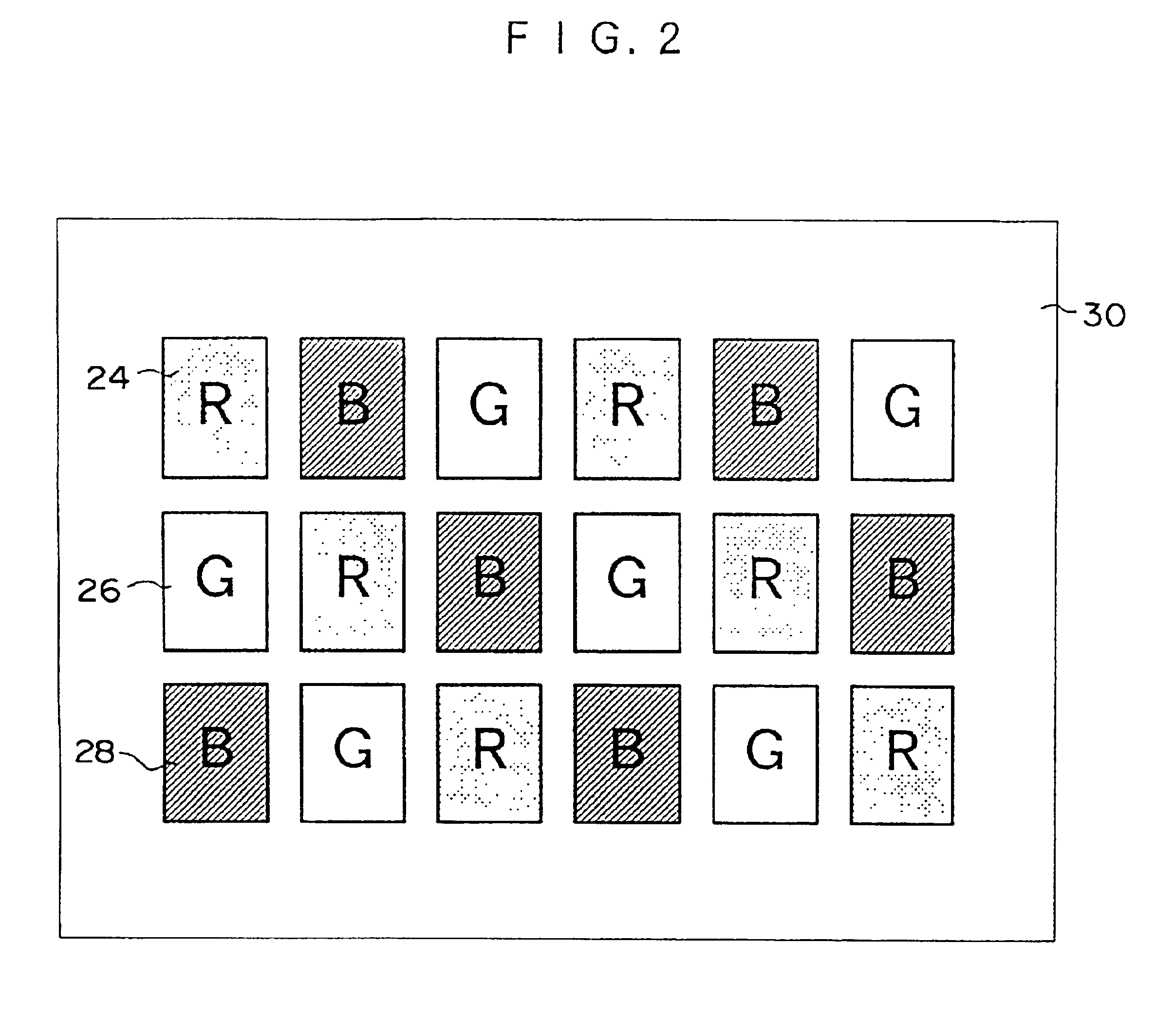
[0040]First, as shown in FIG. 7, the light source 10 includes the organic EL arrays in which a red organic EL array 24R formed by linearly arranging the red organic EL elements 24 in a predetermined direction, a green organic EL array 26G formed by linearly arranging the green organic EL elements 24 in a predetermined direction, and a blue organic EL array 28B formed by linearly arranging the blue organic EL elements 28 in a predetermined di...

third embodiment

[0046]Next, a third embodiment of the image recording device of the present invention will be described. The third embodiment is a case in which the organic EL arrays, in which the organic EL elements of R, G, and B are linearly arranged respectively, are used as the light source, and external modulation is carried out by using a liquid crystal light shutter array.

[0047]As shown in FIG. 9, the image recording device includes the light source 10 comprised of the organic EL elements of the respective colors of R, G, and B. The collimator lens 12 is disposed at the light-exiting side of the light source 10 and collimates light beams emitted from the light source 10. A liquid crystal light shutter array 56, which serves as a transmission type light modulator, is disposed at the light-exiting side of the collimator lens 12. The light source 10 and the liquid crystal light shutter array 56 are connected to the controller 16. On the optical axes of the light beams transmitted through the l...


PUM


Abstract

When a recording starting point of a color photosensitive material reaches a position on which light beams are focused by a condenser lens and a reflecting mirror, a light beam is emitted from a red organic EL element of a light source by a controller, and red image data corresponding to a plurality of lines is transferred to a DMD. In accordance with the image data, on-off control of micromirrors of the DMD is carried out, and the red light beam emitted from the light source is made incident on the DMD. When the micromirrors are on, the incident light beam is reflected toward the reflecting mirror. The light beam is focused onto a recording surface of the color photosensitive material by the condenser lens and the reflecting mirror, and red exposure is carried out. Subsequently, green exposure and blue exposure are carried out in the same way.

Description

BACKGROUND OF THE INVENTION[0001]1. Field of the Invention[0002]The present invention relates to an image recording device, and particularly to an image recording device suitable for recording images by exposing, for each color, color photosensitive materials having spectral sensitivity in the visible region.[0003]2. Description of the Related Art[0004]In a full-color image recording device in which light beams emitted from a light source are externally modulated by using a one- or two-dimensional light shutter array, a white lamp such as a tungsten lamp has been conventionally used as the light source. However, in the image recording device in which a white lamp is used as the light source and the light shutter array is used as an external modulation element, the following problems arise: (1) white lamps have low luminous efficiency and cannot obtain the amount of light required to expose color photosensitive materials; (2) due to short life span, white lamps need to be frequently ...

Claims


Application Information

Patent Timeline
Patent Type & Authority Patents(United States)
IPC IPC(8): G02B26/08G03B27/32G02B5/20B41J2/445
CPCG02B5/201G03B27/32G02B26/0841
Inventor HARADA, AKINORI
Owner FUJIFILM HLDG CORP
Why Eureka
Try Eureka