Optical apparatus and device

a technology of optical apparatus and optical elements, applied in the field of optical apparatus and devices, can solve the problems of signal light pulse significantly degraded, signal cannot be properly transmitted, signal transmittance is not flat, etc., and achieve the effect of improving the wavelength characteristic of output ligh

Inactive Publication Date: 2005-05-31
FUJITSU LTD
View PDF18 Cites 6 Cited by
  • Summary
  • Abstract
  • Description
  • Claims
  • Application Information

AI Technical Summary

Benefits of technology

[0054]An object of the present invention is to provide a means for improving the wavelength characteristic of output light to...

Problems solved by technology

Therefore, the time width of the signal light pulses is widened within the optical fiber, which causes distortion.
However, the device that uses the VIPA plate for wavelength dispersion compensation still has a problem that the characteristic of transmittance of a wavelength is not flat, and becomes a periodical characteristic which is asymmetric with respect to the peak of a wavelength within each transparent bandwidth as shown in FIG.
If a device having such a transparent characteristic which is not flat and asymmetric exists on an optical transmission line, distortion occurs in a signal light pulse waveform transmitted from a transmitter, and the signal cannot be properly transmitted.
As a result, a signal light pulse is sig...

Method used


Image

  • Optical apparatus and device
  • Optical apparatus and device
  • Optical apparatus and device

Examples


Embodiment Construction

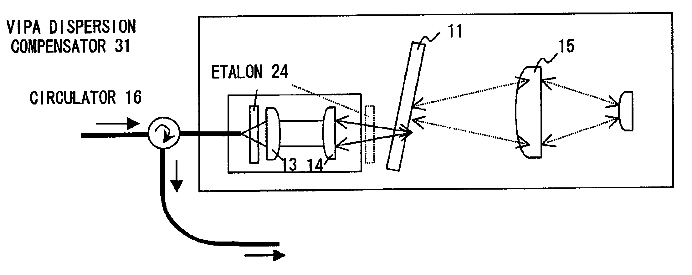
[0083]Preferred embodiments according to the present invention are described in detail below.

[0084]A filter which has an asymmetric periodical characteristic, and is connected to a device comprising VIPA is described below.

[0085]Specifically, an etalon is made to pass diverged or converged light having an angular distribution.

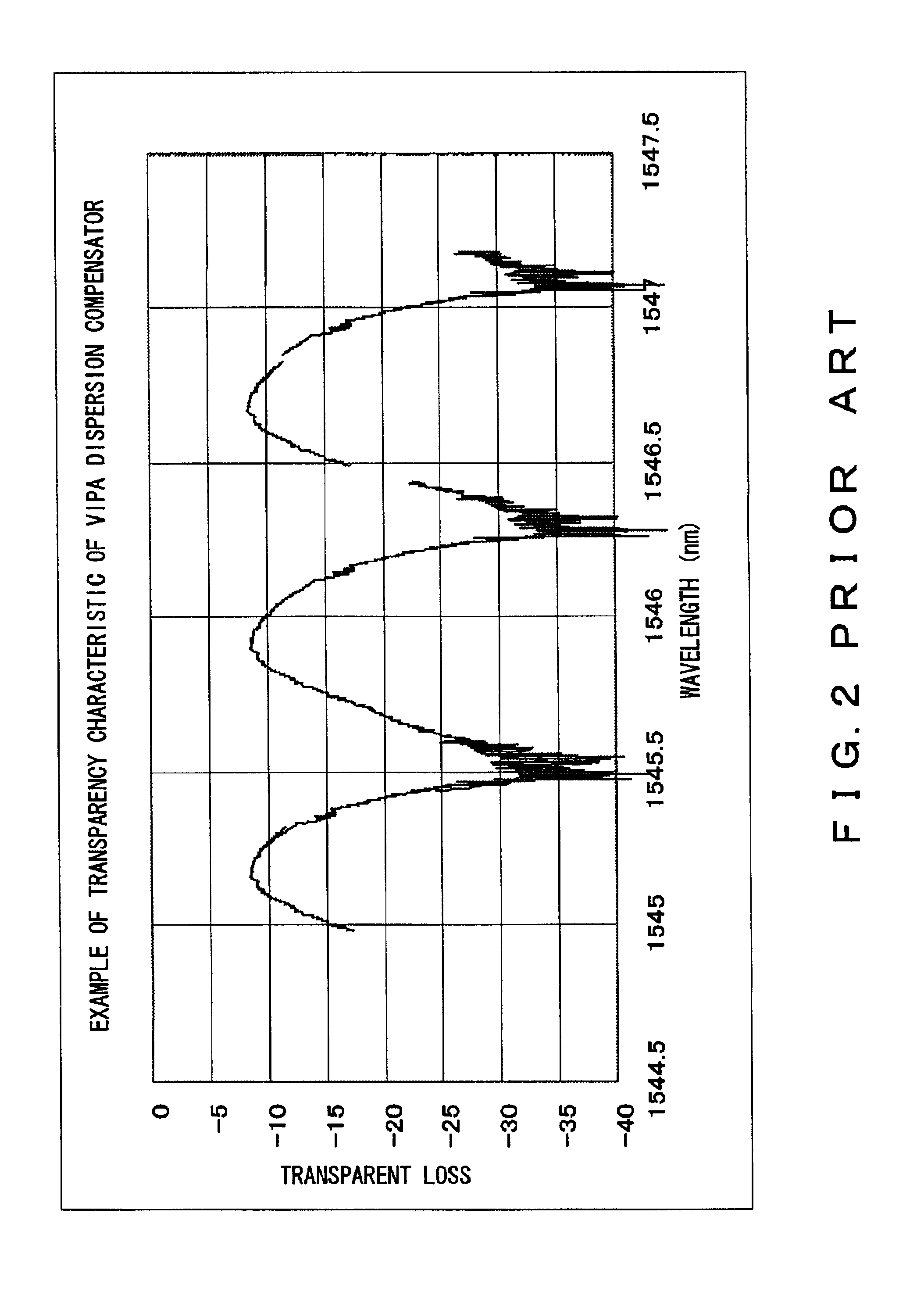
[0086]Generally, the relationship between the transparency characteristic when parallel light is input to the etalon, namely, a transmittance I and a wavelength λ is given by an equation (1). The wavelength λ(central wavelength λc), whose transmittance becomes the maximum, periodically exists, and the transparency characteristic becomes symmetric with reference to the central wavelength as shown in FIG. 3.

I=1 / (1+4R sin2(2πnt cos θ / λ) / (1−R)2  (1)

where R indicates a reflectance of a reflection film, n indicates a refractive index of an etalon gap, t indicates the physical thickness (distance) of the etalon gap, and θ indicates an input angle of light.

λc=2nt...


PUM


Abstract

A VIPA plate having a configuration where a translucent reflection film and a total reflection film are respectively arranged on one side and the other side of a transparent parallel plate can be used as a wavelength dispersion compensator by using a special mirror and a lens. However, the transparency characteristic of the wavelength dispersion compensator using such a VIPA plate is a periodical characteristic which is asymmetric with a central wavelength in a wavelength regime. Accordingly, not parallel light but converged or diverged light having angular dispersion is input to an etalon plate, so that a filter whose transparency characteristic is an asymmetric periodical characteristic which is reverse to the VIPA plate is configured for the central wavelength in the wavelength regime. With this filter, the transparency characteristic of the wavelength dispersion compensator using the VIPA plate is optimized.

Description

BACKGROUND OF THE INVENTION[0001]1. Field of the Invention[0002]The present invention relates to a device generating wavelength dispersion, and a device used to compensate for wavelength dispersion accumulated in an optical fiber transmission line.[0003]To be more specific, the present invention relates to a device which uses a virtually imaged phased array in order to generate wavelength dispersion.[0004]2. Description of the Related Art[0005]A transmitter for transmitting information with light in a conventional optical fiber communications system transmits optical pulses to an optical fiber. Light from the optical fiber is received by a light receiver.[0006]However, the optical fiber has wavelength dispersion, which is also called chromatic dispersion.[0007]The wavelength dispersion changes the pulse width of a signal of the system, so that the quality of the signal is degraded.[0008]To be more specific, the propagation speed of signal light within an optical fiber depends on the...

Claims


Application Information

Patent Timeline
IPC IPC(8): G02B6/34G02B5/28G02B6/293G02B27/00
CPCG02B6/29394G02B6/29358
Inventor MITAMURA, NOBUAKIIZUMI, HIROTOMOKAWAHATA, YUICHI
Owner FUJITSU LTD
Why Eureka
Try Eureka