Optical sensor for measuring physical and material properties

a technology of optical sensors and physical and material properties, applied in the field of optical sensors, can solve the problems of limiting the effect of optical sensors in applications requiring high accuracy and high resolution, limiting the use of optical sensors in applications requiring high resolution, and expensive laboratory equipmen

Inactive Publication Date: 2005-05-31
ROSEMOUNT INC
View PDF31 Cites 95 Cited by
  • Summary
  • Abstract
  • Description
  • Claims
  • Application Information

AI Technical Summary

Problems solved by technology

Unfortunately, effective use of optical sensors in applications requiring high accuracy and high resolution has been limited to expensive laboratory type equipment.
For example, sensor designers have been unable to create optical sensors that accurately measure small scale physical displacements, particularly micron and sub-micron displacements.
Noise in the optical sensor light source, whether laser light or white-light, is a limiting factor since the intensity variations in a single interference band must be accurately measured to provide a high accuracy signal.
Imperfections in the optical interferometer mechanisms in these optical sensors also limits sensor accuracy.
Furthermore, optical sensors fail to measure even these larger displacements if the fringe count memory is lost.
In general, all these devices fall short of addressing the accuracy problems described above.
The combination of frequency noise in the laser mechanism and low gage factor (GF) prevent substantially accurate measurements of small scale displacements.
Frequency noise, i.e., random drift in operating frequency, limits the resolution of these lasers.
Low gage factor results in low resolution and undesirable temperature dependence.
The semiconductor diode lasers used exhibit very large frequency noise components, i.e., the base laser frequency varies randomly over a large bandwidth.
Further, the external cavity used has a low Q due to limited reflectance from the target.
These devices, therefore, are not suitable for measuring small scale displacements in flow systems and other applications.
Furthermore, laser signal drift due to temperature variation and losses in the Bragg reflectors result in loss of accuracy in the measurement of strain.
These devices, however, have no mechanism for measuring displacement or sensing a physical or material parameter.
Thus, while a sensing system based on an optical resonator with a high Q and high gage factor theoretically may provide performance exceeding that of conventional electronic based sensors, none have been shown.

Method used


Image

  • Optical sensor for measuring physical and material properties
  • Optical sensor for measuring physical and material properties
  • Optical sensor for measuring physical and material properties

Examples


Embodiment Construction

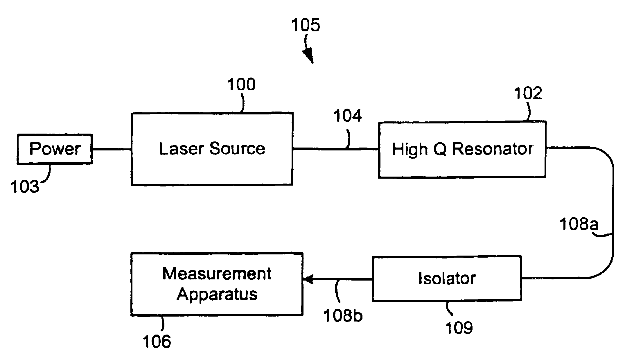
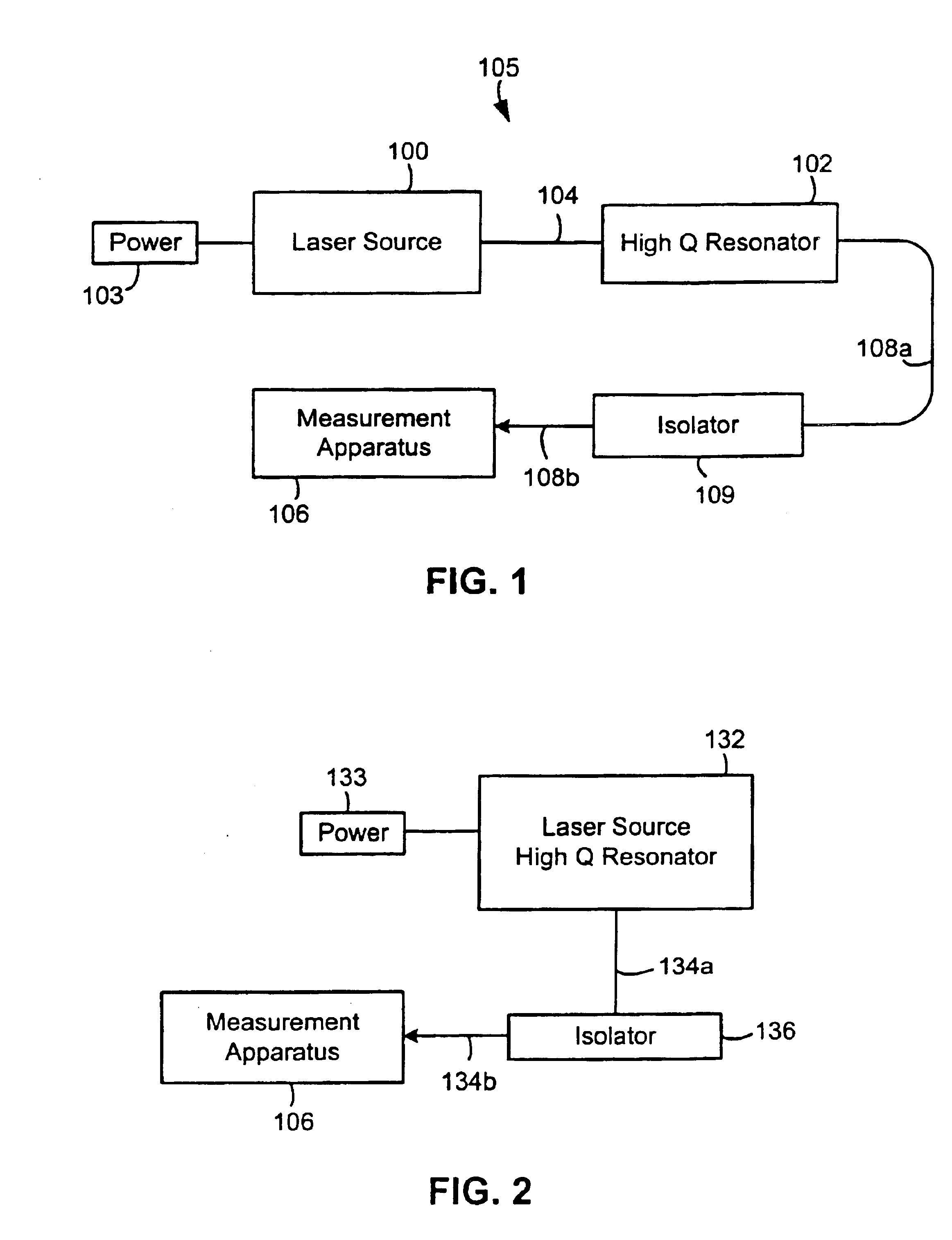
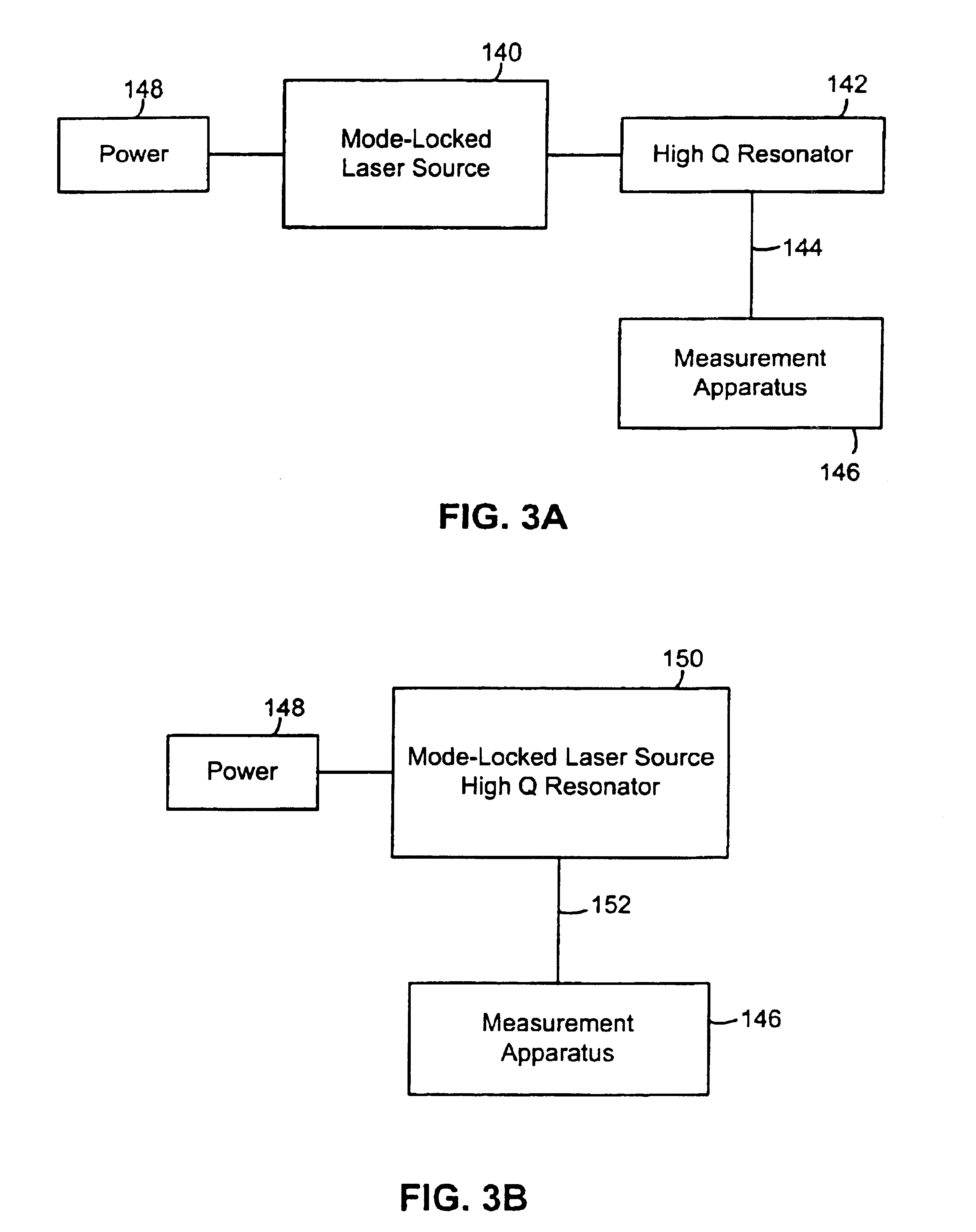
[0037]Below are described various apparatuses and methods that address the above-described problems. Generally, provided are lasers, preferably operating in a pulsed output mode, that produce a laser signal of a repetition rate or frequency modulated by a measurable parameter. By using a mode locked laser conventional high-speed electronics can be used to measure the modulated signal and the repetition rate or frequency of the laser signal can be measured with high resolution. By measuring the frequency of the laser signal, a value for the measurable parameter can be derived.

[0038]In some embodiments, a high Q optical resonator produces the laser signal with a frequency dependant upon the measurable parameter. The high Q resonator can be internal or external to the laser. The devices have lower power consumption and improved accuracy over the state of the art. The devices may be used to measure changes in a measurable parameter or they may be used to make absolute measurements. Furt...


PUM


Abstract

An optical medium having a cavity that defines a variable gap is provided. The optical medium is used in an optical sensor, laser, and variable frequency resonator, by way of example. The cavity is physically altered in response to changes in a measurable parameter like pressure, temperature, force, flow rate, and material composition. The optical medium is characterized in some embodiments by having a cavity disposed near or within a high Q optical resonator. The optical resonator can be formed by various structures of which Bragg reflector cavities, ring resonators, microdiscs, and microspheres are examples. The optical resonator is preferably coupled to a laser source. The altering of the cavity affects the resonance condition within the optical resonator and thereby the laser signal of the system. If the laser source is a mode locked laser, the repetition rate of the pulse train changes in response to changes in the measurable parameter. If the laser source is a CW source the frequency of the laser signal is dependent upon a measurable parameter.

Description

RELATED APPLICATION[0001]This application claims the benefit of U.S. Provisional Application No. 60 / 253,703, filed Nov. 28, 2000; U.S. Provisional Application No. 60 / 253,704, filed Nov. 28, 2000; and U.S. Provisional Application No. 60 / 253,705, filed Nov. 28, 2000, the specifications of which are all incorporated herein by reference.FIELD OF THE INVENTION[0002]The present disclosure relates generally to optical sensors and, more specifically, to optical sensors used to measure parameters commonly measured in industrial process or flow systems, parameters like pressure, temperature, flow rate, strain, and material composition.BACKGROUND OF THE PRIOR ART[0003]Sensors that use fiber optics to provide sensor power and / or transmit sensed information are known. These sensors are useful where conventional electrical sensors that use wires to transmit power and information cannot be used due to limitations such as noise susceptibility or the temperature limits of electronics. Optical sensor...

Claims


Application Information

Patent Timeline
Patent Type & Authority Patents(United States)
IPC IPC(8): G01D5/353G01D5/26H01S3/00H01S3/06H01S3/08H01S3/083H01S3/091H01S3/0933H01S3/10H01S5/14H01S5/183
CPCG01D5/35312G01D5/35341
Inventor FRICK, ROGER L.
Owner ROSEMOUNT INC
Why Eureka
Try Eureka