All-digital FM stereo demodulator and demodulation method

a technology of fm stereo demodulator and all-digital fm, which is applied in the direction of broadcast circuit arrangement, broadcast system receiving, broadcast with distribution, etc., can solve the problems of need for external vco or vcxo, and inability to easily integrate with digital signal-processing circuits

Inactive Publication Date: 2005-05-31
MITSUBISHI ELECTRIC CORP
View PDF11 Cites 11 Cited by
  • Summary
  • Abstract
  • Description
  • Claims
  • Application Information

AI Technical Summary

Benefits of technology

[0005]An object of the present invention is to provide a digital FM stereo demodulator that does not require precise control of its input sampling timing.

Problems solved by technology

The need for a digital-to-analog converter and analog filter for the error signal is a disadvantage, because these components take up space, and the analog filter in particular cannot easily be integrated with digital signal-processing circuits.
The need for an external VCO or VCXO is likewise a disadvantage.
The effect of these disadvantages is to increase the parts count and manufacturing cost of the conventional FM stereo demodulator.

Method used


Image

  • All-digital FM stereo demodulator and demodulation method
  • All-digital FM stereo demodulator and demodulation method
  • All-digital FM stereo demodulator and demodulation method

Examples


first embodiment

[0050

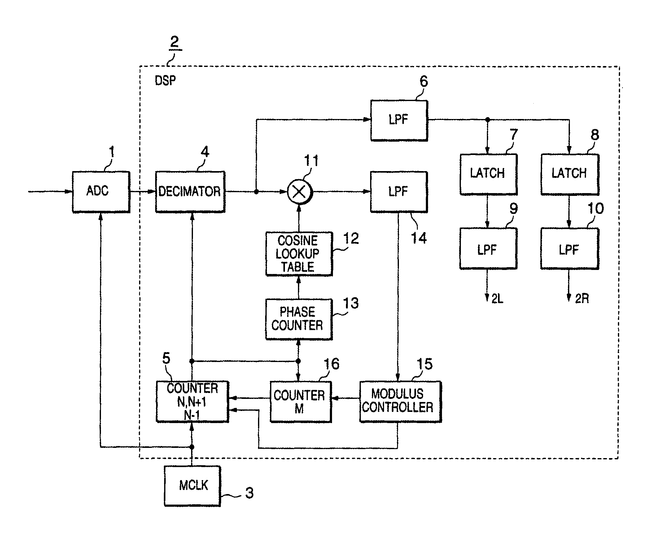
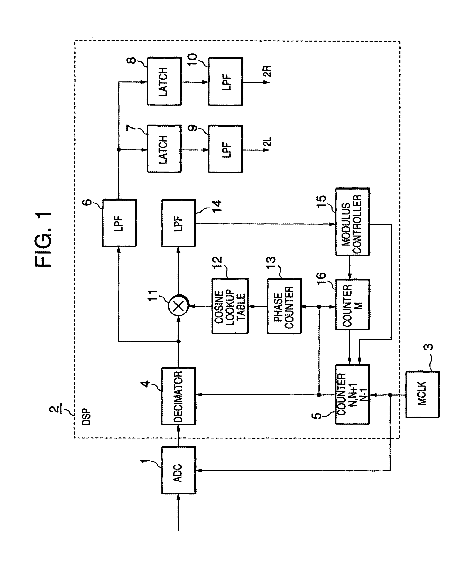
[0051]Referring to FIG. 1, the first embodiment of the invention is a digital FM stereo demodulator comprising an analog-to-digital converter (ADC) 1, a digital signal processor (DSP) 2, and a master clock generator (MCLK) 3. The DSP 2 includes a decimator 4, a first variable-modulus counter 5, low-pass filters 6, 9, 10, 14, a first latch 7, a second latch B, a multiplier 11, a cosine look-up table 12, a phase counter 13, a modulus controller 15, and a second variable-modulus counter 16.

[0052]Although the internal components of the DSP 2 are shown as hardware blocks, some or all of these blocks may be replaced by software modules with equivalent functions. This remark also applies to the succeeding embodiments.

[0053]The master clock generator 3 generates a master clock signal with a fixed frequency. The master clock signal is supplied to the ADC 1 and DSP 2. The ADC 1 operates at a sampling frequency equal to the master clock frequency, generating input samples of the stereo co...

second embodiment

[0072

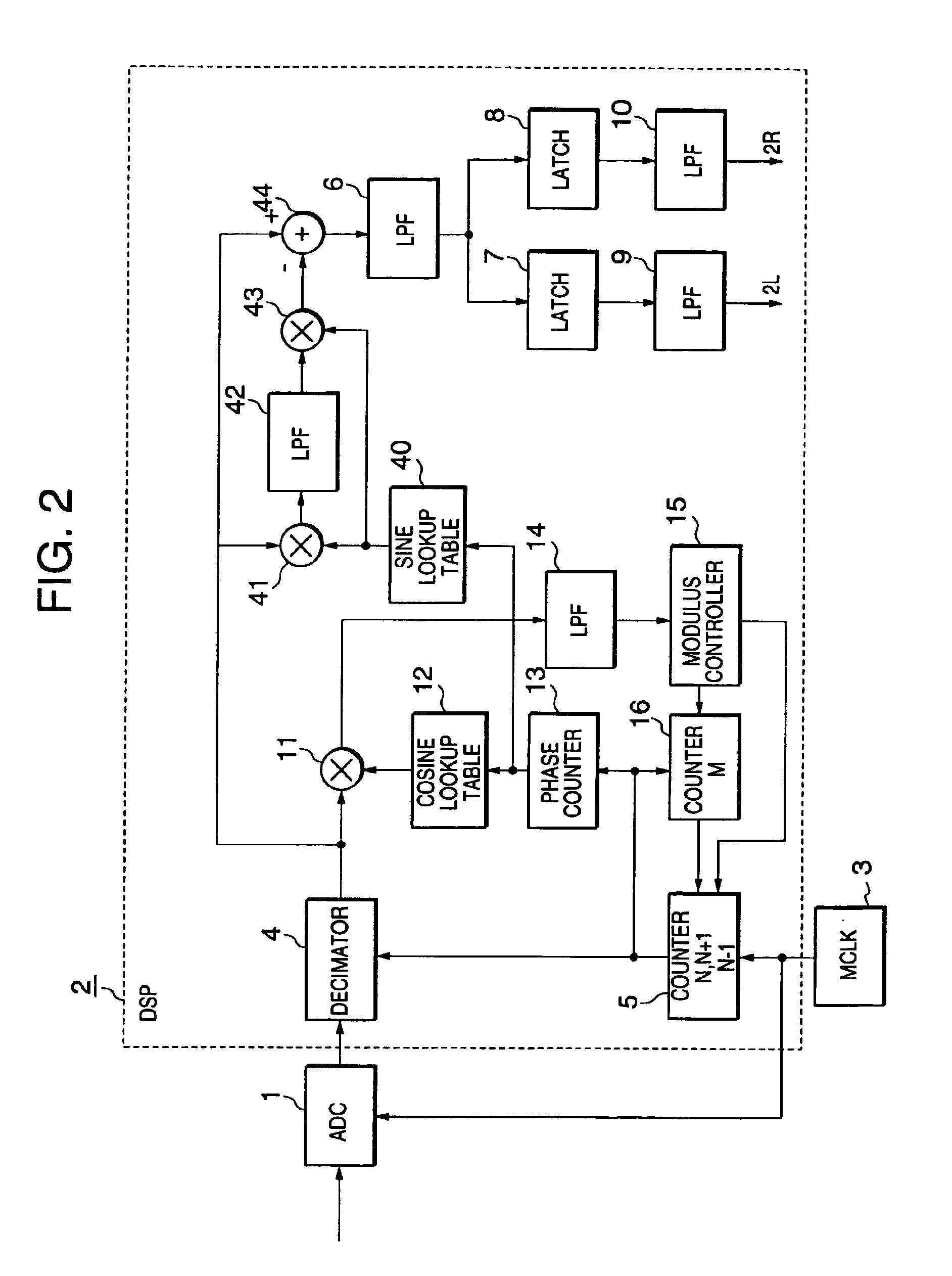
[0073]FIG. 2 shows a digital FM stereo demodulator illustrating a second embodiment of the invention. Descriptions of elements 1 to 16 will be omitted, as these elements are similar to the corresponding elements in the first embodiment. The additional elements in the second embodiment are a sine look-up table 40, a second multiplier 41, another low-pass filter 42, a third multiplier 43, and an adder 44.

[0074]Elements 1 to 16 operate as described in the first embodiment, synchronizing the internal sampling timing according to the pilot signal, and selecting suitable internal samples for the left-channel and right-channel stereo audio data.

[0075]The other elements detect the amplitude of the pilot signal, generate a replica of the pilot signal, and subtract the replica from the internal sample values before they undergo low-pass filtering and left-right channel selection. Cancellation of the pilot signal in this way relaxes the performance requirements of the first and second low...

third embodiment

[0082

[0083]FIG. 3 shows a digital FM stereo demodulator illustrating a third embodiment of the invention. Descriptions of elements 1 to 3, 6 to 8, 9 to 14, and 16 will be omitted, as these elements are similar to the corresponding elements in the first embodiment. The new elements are a modulus and coefficient controller 17, an interpolation filter 20, a filter coefficient (Coeff.) table 21, a filter coefficient selector 22, a filter operation (Opr.) controller 23, and a clock frequency divider or counter 24.

[0084]The third embodiment uses the interpolation filter 20 to interpolate internal samples between the samples received from the ADC 1, varies the interpolation locations according to the phase error signal, and demodulates the interpolated sample data in place of the input sample data. The modulus and coefficient controller 17 designates the counting modulus of variable-modulus counter 16 as described in the first embodiment. The modulus and coefficient controller 17 also inst...


PUM


Abstract

A stereo composite signal including a pilot signal is demodulated by processing input samples to obtain internal samples having variable sampling timings, synchronizing these sampling timings with the pilot signal, and digitally processing the internal samples to obtain stereo audio data. The internal samples may be obtained from the input samples by decimation or interpolation. Since the sampling frequency and sampling timing of the input samples do not have to be precisely controlled, no voltage-controlled oscillator is needed, and the demodulator can easily be incorporated into a monolithic integrated circuit.

Description

BACKGROUND OF THE INVENTION[0001]This invention relates to a frequency-modulation (FM) stereo demodulator based entirely on digital signal processing, for use in an FM audio broadcast receiver.[0002]FM stereo demodulators of the switching type, with analog circuitry, have long been used in FM audio broadcast receivers, but as the density of integrated circuits rises, digital circuit configurations are becoming advantageous due to their small size and their compatibility with digital broadcast receiver circuits.[0003]The input to a digital FM stereo demodulator is conventionally a stereo composite signal that has been sampled in synchronization with a sampling clock output by a voltage-controlled oscillator (VCO) or voltage-controlled crystal oscillator (VCXO). If the stereo composite signal is sampled at the right times, it can be demodulated to left-channel and right-channel stereo audio signals simply by selection of certain subsets of the input samples. The functions of a convent...

Claims


Application Information

Patent Timeline
Patent Type & Authority Patents(United States)
IPC IPC(8): H03D3/00H04B1/16
CPCH03D3/006
Inventor TAURA, KENICHITSUJI, MASAYUKITSUJISHITA, MASAHIROISHIDA, MASAYUKI
Owner MITSUBISHI ELECTRIC CORP
Why Eureka
Try Eureka