
Fiber tip based sensor system for acoustic measurements

a sensor system and fiber optic technology, applied in the field of acoustic measurement, can solve the problems of limiting the application of these types of sensors, and affecting the accuracy of the measuremen

Inactive Publication Date: 2005-05-31
UNIV OF MARYLAND
View PDF4 Cites 43 Cited by
  • Summary
  • Abstract
  • Description
  • Claims
  • Application Information

AI Technical Summary

Benefits of technology

[0025]It is another object of the present invention to provide fiber tip based Fabry-Perot sensor systems for active acoustic control where fiber tip sensors are designed for acoustic pressure and air particle velocity measurements internal / external to an enclosure, and further to provide acceleration measurements.
[0026]Another object of the present invention is to provide a multi-sensor fiber tip based active acoustic control system in which a digital phase demodulation system is based on a multi-step phase-stepping technique to decode the optical intensity signal into optical phase signals.

Problems solved by technology

In the design of modem transportation vehicles, structural vibration and interior noise have become important problems that need to be addressed.
For example, in helicopter systems control of sound transmission into enclosed spaces is an important issue.
However, the sensor bandwidth was found to be limited and in addition, the sensor was found to have low sensitivity due to the high Young's modules of silica resulting in “acoustically induced strains” which also limit the application of these types of sensors.
Intensity modulated sensors offer simplicity of design and ease of implementation, however they suffer from problems of limited sensitivity, low dynamic range and drift, due to uncertainty fluctuation.
However, complexity and bulkiness of known velocity microphones makes them difficult to use effectively in ASAC systems.
Although the size of the sensor was “small” compared to many commercially available velocity probes, it was shown that such a sensor could lead to errors if there is any mismatching between the different pressure microphones.
There is also the potential for interference, since the microphones are housed together in a small volume.
This interference may significantly affect the sensor signal-to-noise ratio, especially at low sound pressure levels.

Method used


Image

  • Fiber tip based sensor system for acoustic measurements
  • Fiber tip based sensor system for acoustic measurements
  • Fiber tip based sensor system for acoustic measurements

Examples


Embodiment Construction

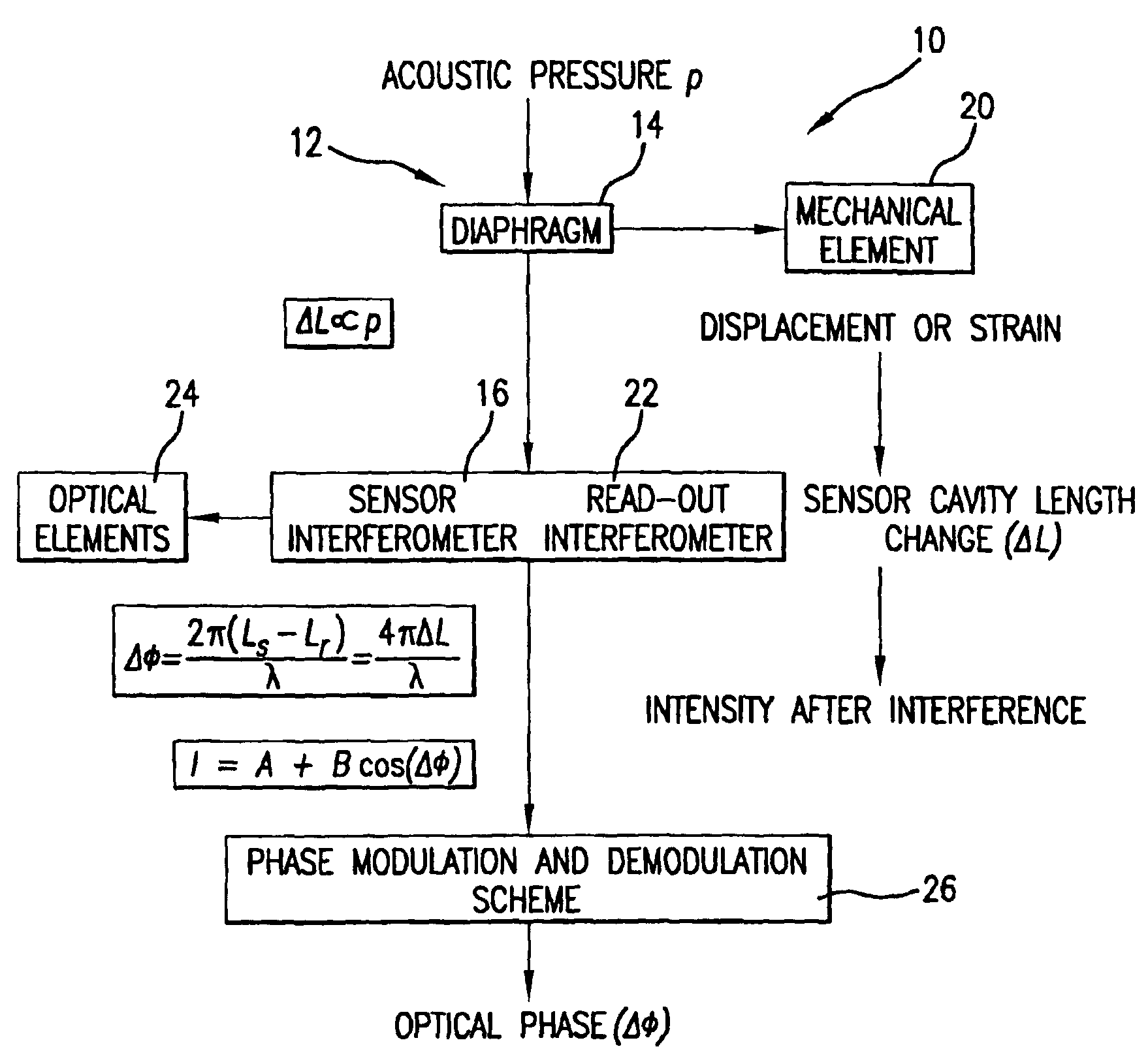
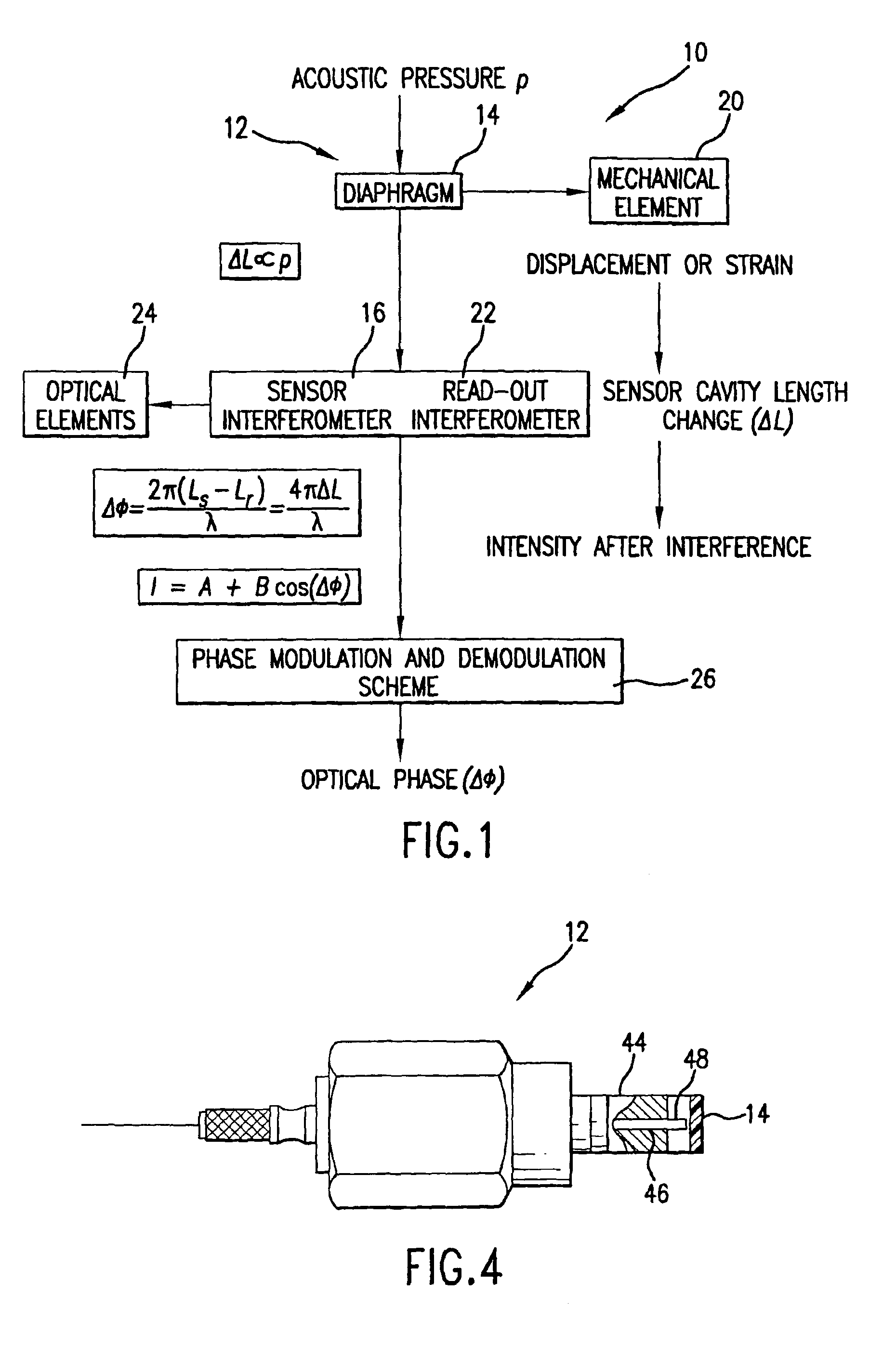
[0067]Referring to FIG. 1, sensor system 10 for the acoustic measurements includes a sensor 12 having a diaphragm 14 and a sensor interferometer 16. In order to determine the parameters of a mechanical element 20 which undergoes displacement or strain, the diaphragm 14 of the sensor 12 oscillates under the influence of acoustic pressure P generated by the mechanical element 20. The sensor interferometer 16 is a Fabry-Perot interferometer. The cavity length of the interferometer, ΔL changes according to diaphragm fluctuations which permits determination of the mechanical element's parameters. Therefore, the cavity length change ΔL is the parameter which may serve to determine the acoustic pressure P.

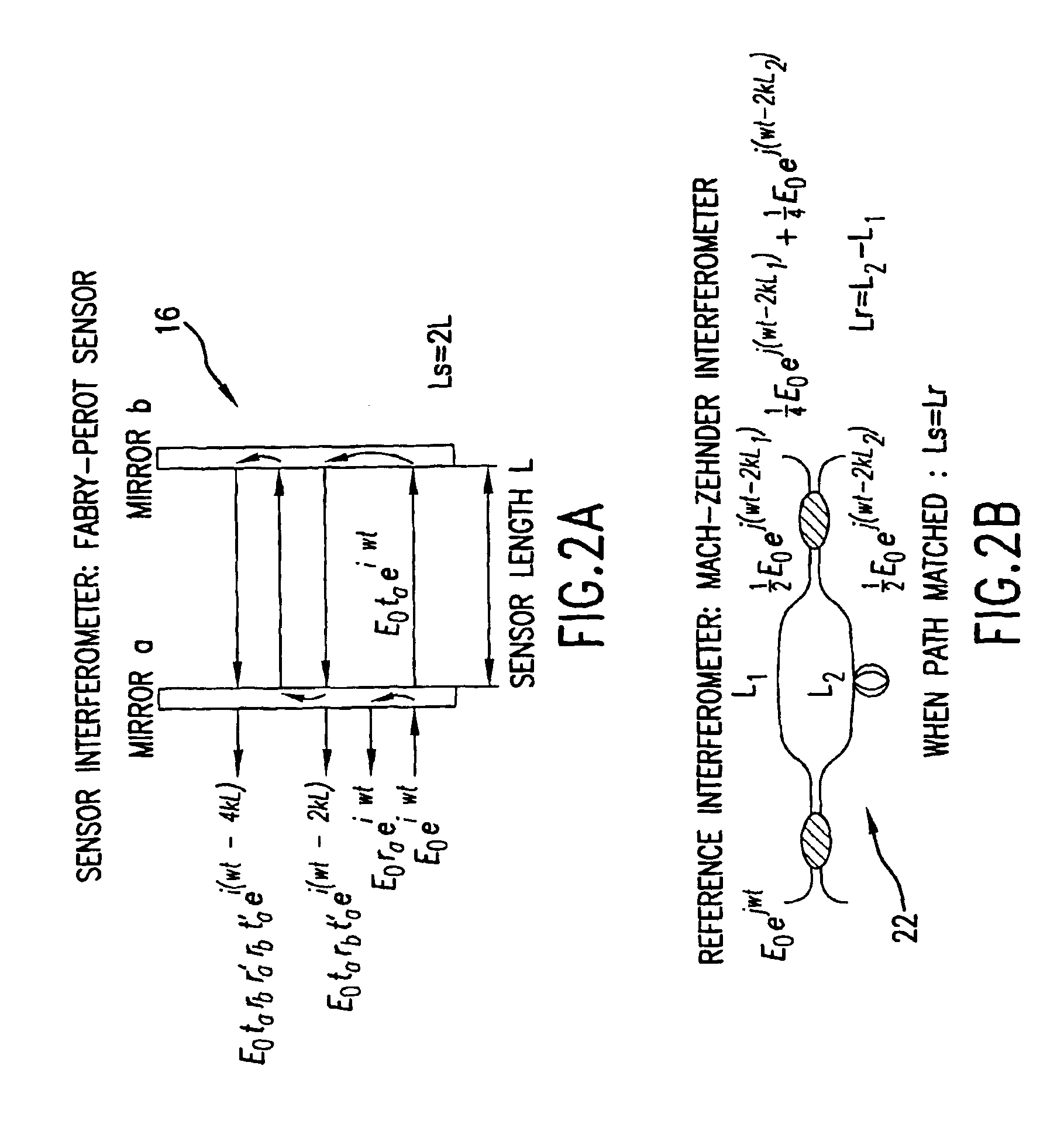
[0068]A read-out interferometer 22 is path-matched to the sensing interferometer 16 as will be described in detail infra. The cavity length change ΔL signal is coupled to optical elements 24 which include photodetectors. The received signal (intensity at the output of the photodetectors) ...


PUM


Abstract

A fiber optic sensor system for acoustic measurements over a 6 kHz bandwidth, the design of which allows for multiplexity of the input side of the system, and where the optical part of the system is based on low coherence fiber-optic interferometry techniques which has a sensor Fabry-Perot interferometer and a read-out interferometer as well, that allows a high dynamic range and low sensitivity to the wavelength fluctuation of the light source, as well as the optical intensity fluctuations. A phase modulation and demodulation scheme takes advantage of the Integrated Optical Circuit phase modulator and multi-step phase-stepping algorithm for providing for high frequency and real time phase signal demodulation. The system includes fiber tip based Fabry-Perot sensors which have a diaphragm, which is used as the transducer. Pressure microphone, velocity sensor, as well as accelerometer, are built based on the fiber tip based Fabry-Perot sensors.

Description

STATEMENT REGARDING FEDERALLY SPONSORED RESEARCH OR DEVELOPMENT[0001]This invention was made with government support under Contract Number DAAH04-96-1-0334 awarded by the U.S. Army Research Office and Contract Number CMS23222 awarded by the National Science Foundation. The government has certain rights in the invention.FIELD OF THE INVENTION[0002]The present invention relates to acoustic measurement and more in particular, to fiber tip based fiber optic acoustic sensors for measurement of acoustic fields in the frequency range of 50 Hz to 7.5 kHz.[0003]Even more in particular, the present invention relates to fiber tip based low-finesse Fabry-Perot sensors system for acoustic pressure, velocity and acceleration measurements, designed to work in an acoustic control system with multiple sensor inputs.[0004]Further, the present invention relates to a fiber tip based Fabry-Perot sensor system for detection of the acoustically induced optical phase shift by using an interference techniqu...

Claims


Application Information

Patent Timeline
Patent Type & Authority Patents(United States)
IPC IPC(8): G01D5/353G01D5/26G01H9/00G02B6/34
CPCG01D5/35303G01H9/006G02B6/4246G02B6/29358G02B6/2935
Inventor BALACHANDRAN, BALAKUMARYU, MIAOAL-BASSYIOUNI, MOUSTAFA
Owner UNIV OF MARYLAND
Learn More