Device for controlling a hydraulic actuator

Inactive Publication Date: 2005-05-31
BOSCH REXROTH AG
View PDF16 Cites 22 Cited by
  • Summary
  • Abstract
  • Description
  • Claims
  • Application Information

AI Technical Summary

Benefits of technology

[0005]As a result of the integration of the subassemblies for the control of the drive into the hydraulic valve, the expenditure on cabling is reduced, in particular the length of the signal lines from the sensors for the state variables of the drive is shortened. At the same time, the amount of space required in the switch cabinet is reduced, since only space to accommodate the higher-order controller is needed there. Furthermore, it is possible to assemble and pretest the drive for one axis as an entire system. Since only the supply lines have to be connected to said system during installation, for example in a machine tool, the commissioning costs are reduced considerably.
[0006]By constructing the electronic controller as a freely programmable sequence controller, high flexibility results. By means of interfaces to a local bus system, to which further devices of identical construction can be connected, the latter can be networked with one another. This networking permits general exchange of data between a plurality of drives, for example in order to implement synchronous running control systems. The local bus system results in an automation concept which can be scaled in modular fashion. Interfac

Problems solved by technology

This leads to an expenditure on circuitry which is not inconsiderable.
Added to this is the fact that, because of the large number of electric

Method used


Image

  • Device for controlling a hydraulic actuator
  • Device for controlling a hydraulic actuator
  • Device for controlling a hydraulic actuator

Examples


Embodiment Construction

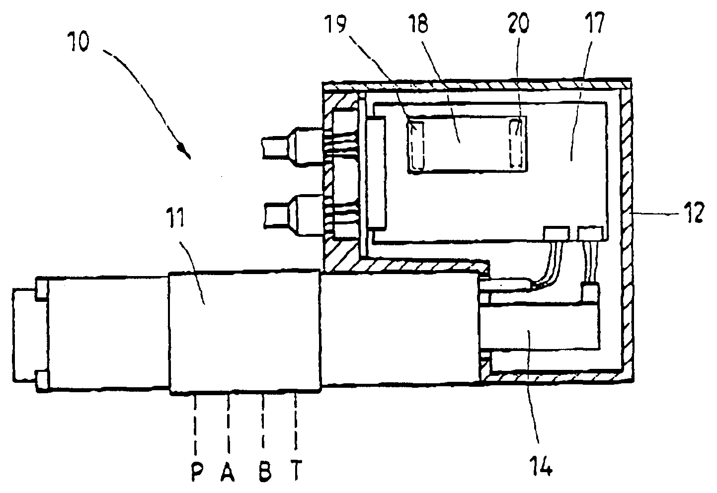
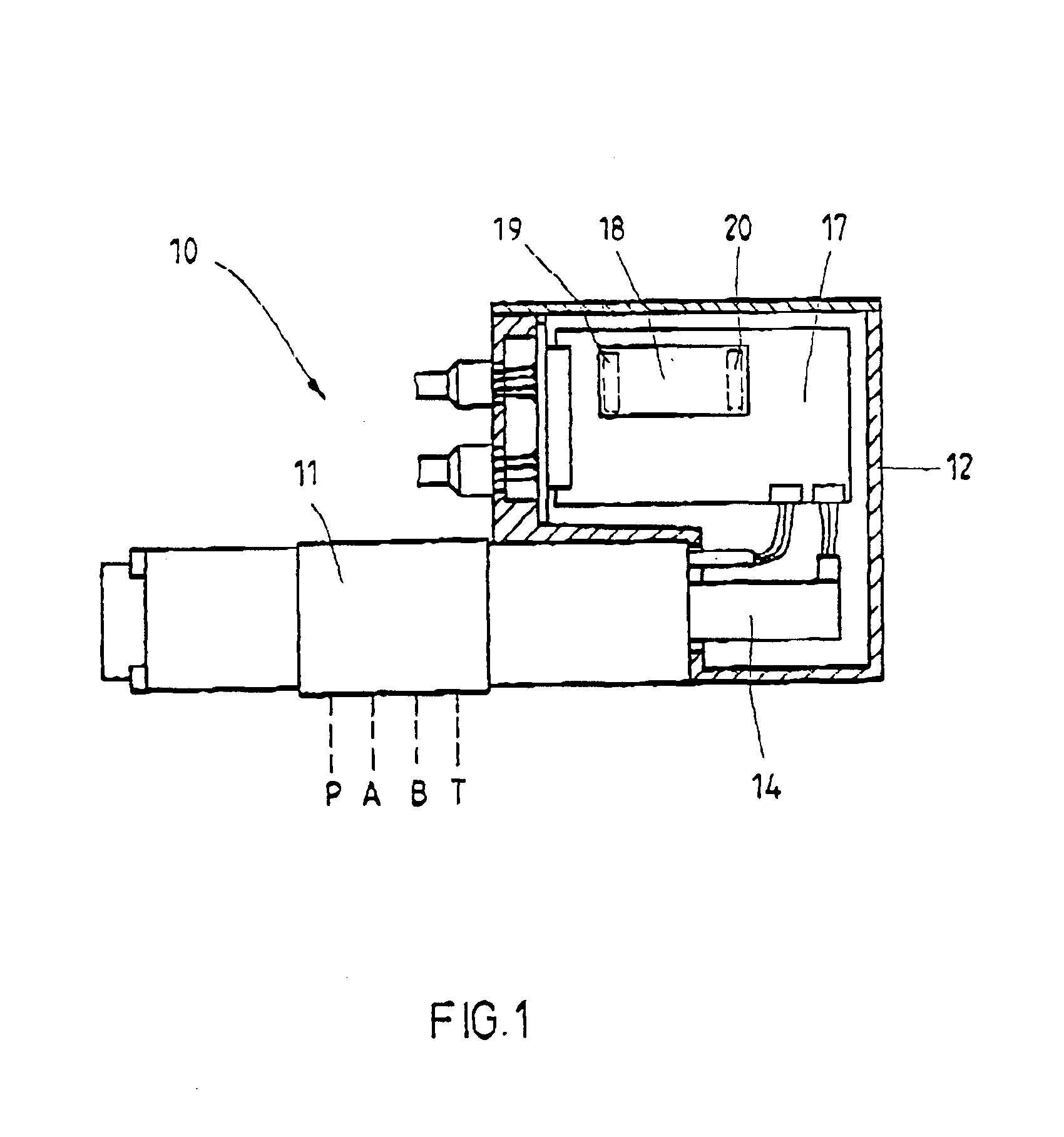
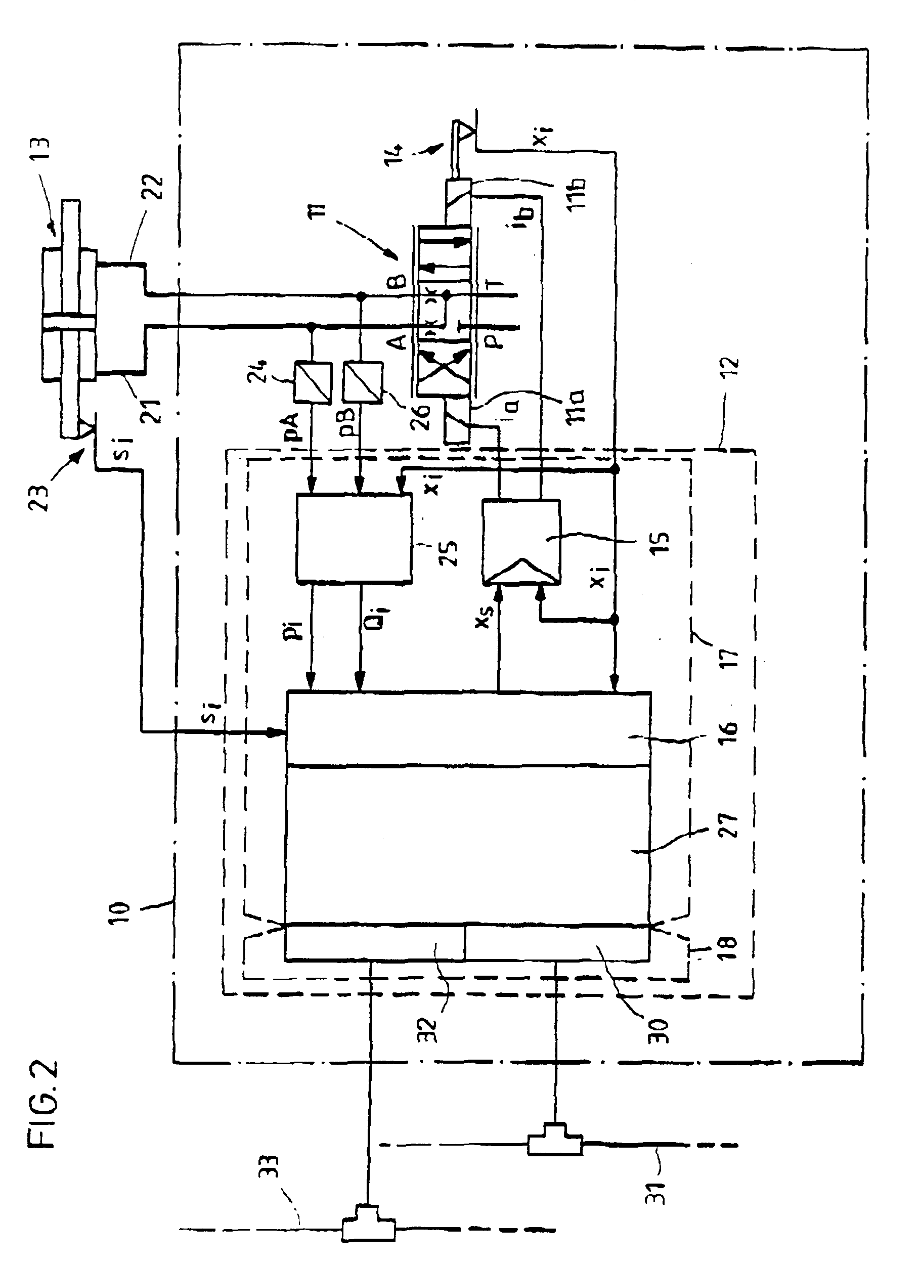
[0011]FIG. 1 shows the view of a device 10 for controlling a hydraulic actuator. A housing 12 is held on a hydraulic valve 11. The valve 11 is illustrated as viewed from the side. The valve 11 controls the flow of pressure medium from a pump to a hydraulic actuator and back from the latter to a tank. In the exemplary embodiment, the actuator is a hydraulic cylinder which, in FIGS. 2 and 3, is illustrated as a double-ended cylinder 13. Alternatively, the actuator used may be a differential cylinder or a hydraulic motor. The hydraulic connections of the valve 11 are designated by P for the pump connection, T for the tank connection and A and B for the connections to the double-ended cylinder 13. A displacement sensor 14 for the position x of the valve piston projects into the housing 12. The displacement sensor 14 converts the position x of the valve piston into an electrical signal xi which, in the controller 15 illustrated in FIG. 2, is supplied as the actual value. The components o...


PUM


Abstract

A device for controlling a hydraulic actuator includes an electrically operated valve that controls the flow of a pressure medium in the actuator in response to the operations of three controllers. A first of the controllers designates a position of a piston of the valve. A second of the controllers commands movement of the actuator. And a third of the controllers electronically controls a sequence of movements of the actuator. The three actuators are arranged in a common housing located on the valve.

Description

FIELD AND BACKGROUND OF THE INVENTION[0001]The invention relates to a device for controlling a hydraulic actuator, comprising an electrically operated valve which controls the flow of pressure medium to and from the actuator, and comprising a controller, integrated into the housing of the valve or held on the latter in its own housing, for the position of the valve piston.[0002]A device of this type comprising an electrically operated hydraulic valve is disclosed by DE 195 30 935 C2. A displacement sensor for the position of the valve piston converts the position of the valve piston into an electrical signal, which is supplied to a position controller as actual value. The controller for the position of the valve piston is arranged in its own housing, which is held on the housing of the valve. The controller ensures that the valve piston follows a position set point, which is supplied to the controller as an electrical input variable, for example in the form of a voltage. In this cas...

Claims


Application Information

Patent Timeline
IPC IPC(8): F15B21/08F15B21/00F15B13/04F15B13/00
CPCF15B21/08F15B2013/0409
Inventor KOCKEMANN, ALBERT
Owner BOSCH REXROTH AG
Why Eureka
Try Eureka