Method and arrangement for limiting the speed of a vehicle

a technology for limiting the speed of a vehicle, which is applied in the direction of braking systems, process and machine control, instruments, etc., can solve the problems of easy limiting of the driver command, severe impact on driving comfort, and unwanted overshoots, so as to achieve the effect of increasing driving comfort and not affecting driving comfor

Inactive Publication Date: 2005-05-31
ROBERT BOSCH GMBH
View PDF2 Cites 4 Cited by
  • Summary
  • Abstract
  • Description
  • Claims
  • Application Information

AI Technical Summary

Benefits of technology

[0003]With respect to the above, the method and arrangement of the invention afford the advantage that a maximum permissible acceleration is determined which is proportional to the difference between an actual speed and the limit speed and that a limit value for an output quantity of a drive unit of the vehicle is determined from the maximum permissible acceleration via a vehicle dynamics equation in dependence upon a running resistance. The magnitude of this limit value for limiting the speed of the vehicle to the limit speed may not be exceeded. In this way, a speed limiting function without an integral component may nonetheless be precisely realized in steady state. With the described control algorithm, the limit speed can be approached very comfortably via an exponential function whose time constant is applicable via the proportional amplification factor of the speed deviation. With the aid of the vehicle dynamics equation, a conversion between the maximum permissible acceleration and the limit value for the output quantity of the drive unit of the vehicle is possible.
[0004]It is especially advantageous when the output quantity is pregiven via a minimal selection between a value derived from a driver command or derived from a road speed control of the limit value. In this way, it is ensured that the output quantity of the drive unit for maintaining the maximum permissible acceleration is limited.
[0005]A further advantage is that a desired speed, which is pregiven by the road speed control, is limited to the limit speed. In this way, a conflict between the road speed control and the speed limit function is avoided and a run-up of an integral component, which is possibly present in the road speed controller, is avoided. In this way, it is prevented that, when switching off the speed limiting function, unwanted overshoots in the road speed control occur. In this way, the driving comfort is not affected.
[0006]It is especially advantageous when the limiting of the speed is lifted in dependence upon the driver command especially by means of a kick down. In this way, the speed limiting function can be switched off or deactivated when this is wanted for reasons of safety, for example, for a passing operation by the driver.
[0007]A further advantage is that the limit value for the output quantity of the drive unit becomes effective only within a pregiven range about the limit speed. In this way, it is ensured that the approach of the actual speed to the limit speed does not take place abruptly so that the driving comfort is increased. In contrast, outside of the pregiven range, any desired speed course, which is wanted by the driver, is possible.

Problems solved by technology

A limiting of the driver command is easily carried out in vehicles having an electronic accelerator pedal.
If, however, a road speed control and a speed limiting function are simultaneously active, then this can lead to conflicts, for example, when, on the one hand, the road speed control is controlled to 80 km / h but, on the other hand, the upper limit speed is at 50 km / h.
The controller of the road speed control and the controller of the speed limiting function could then run counter to each other and possibly available integrators of the controller would assume large values which could lead to unwanted overshoots when switching off one of the two controllers.
In this way, the driving comfort could be severely affected.

Method used


Image

  • Method and arrangement for limiting the speed of a vehicle
  • Method and arrangement for limiting the speed of a vehicle
  • Method and arrangement for limiting the speed of a vehicle

Examples


Embodiment Construction

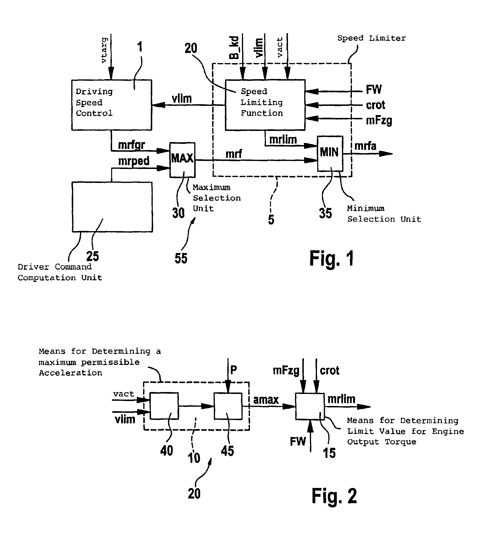
[0013]In FIG. 1, reference numeral 55 identifies a control for adjusting a speed of the motor vehicle having a drive unit. The drive unit includes, for example, an internal combustion engine or an electric motor or is based on any other desired alternative drive concept. When using an internal combustion engine, the engine can, for example, be a spark-ignition engine or a diesel engine. In the following, it is assumed by way of example, that the drive unit includes an internal combustion engine.

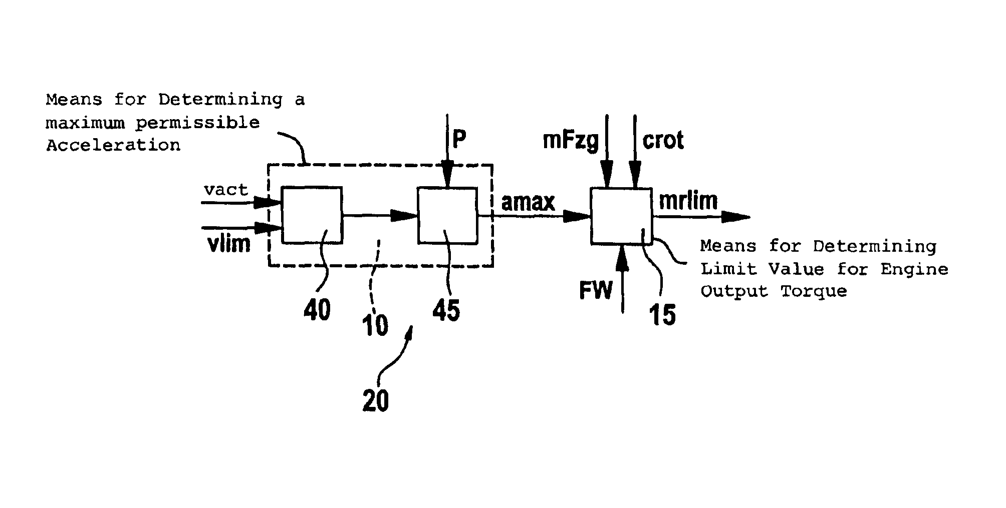
[0014]The control 55 can, for example, be integrated in an engine control of the vehicle and can be realized as hardware and / or as software. The control 55 includes an arrangement 5 for limiting the speed of the vehicle. The arrangement 5 therefore defines a speed limiter. The speed limiter 5 includes a speed limiting function 20 to which a limit speed vlim is supplied and this speed limiting function determines a limit value for an output quantity of the drive unit in dependence upon the lim...


PUM


Abstract

A method and an arrangement are suggested for limiting the speed of a vehicle to a limit speed with the arrangement not needing an integral component and nonetheless being precise at steady state. A maximum permissible acceleration proportional to the difference between an actual speed and the limit speed is determined. From the maximum permissible acceleration, a limit value for an output quantity of a drive unit of the vehicle is determined by means of a vehicular dynamic operation equation in dependence upon the running resistance. The magnitude of the limit value for limiting the speed of the vehicle to the limit speed may not be exceeded.

Description

BACKGROUND OF THE INVENTION[0001]In addition to the functions for controlling a pregiven speed, also functions for limiting to a pregiven upper speed threshold or limit speed via a speed limiting function are known for gasoline-control apparatus and diesel-control apparatus. The functions for controlling speed are, for example, done by means of a road speed controller or a pregiven distance controlled, for example, by means of a vehicle dynamics control. Such applications include all limitations on the upper limit speed such as maximum speeds, which are inputted by the driver via an operator-controlled apparatus, or automatically pregiven limit speeds based on monitoring functions and comfort functions such as traffic sign recognition, exceeding maximum weight, pressure loss in the tires, detection of travel in a curve.[0002]A limiting of the driver command is easily carried out in vehicles having an electronic accelerator pedal. If, however, a road speed control and a speed limitin...

Claims


Application Information

Patent Timeline
Patent Type & Authority Patents(United States)
IPC IPC(8): B60K31/04B60K31/02B60K31/00
CPCB60K31/047B60W2720/106B60W2530/16B60W30/146
Inventor KUSTOSCH, MARIOMUEHLBAUER, CHRISTIANGLORA, MICHAEL
Owner ROBERT BOSCH GMBH
Why Eureka
Try Eureka